|
Time-interleaved ADC
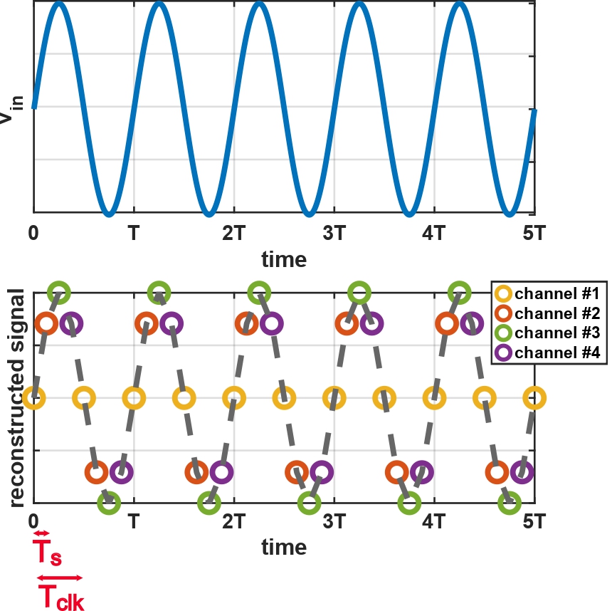
Time interleaved (TI) ADCs are Analog-to-digital converter, Analog-to-Digital Converters (ADCs) that involve ''M'' converters working in parallel. Each of the ''M'' converters is referred to as sub-ADC, channel or slice in the literature. The time interleaving technique, akin to multithreading in computing, involves using multiple converters in parallel to sample the input signal at staggered intervals, increasing the overall sampling rate and improving performance without overburdening the single ADCs. History Early concept The concept of time interleaving can be traced back to the 1960s. One of the earliest mentions of using multiple ADCs to increase sampling rates appeared in the work of Bernard M. Oliver and Claude Shannon, Claude E. Shannon. Their pioneering work on communication theory and sampling laid the groundwork for the theoretical basis of time interleaving. However, practical implementations were limited by the technology of the time. Development In the 1980s, signific ... [...More Info...] [...Related Items...] OR: [Wikipedia] [Google] [Baidu] |
Analog-to-digital Converter
In electronics, an analog-to-digital converter (ADC, A/D, or A-to-D) is a system that converts an analog signal, such as a sound picked up by a microphone or light entering a digital camera, into a Digital signal (signal processing), digital signal. An ADC may also provide an isolated measurement such as an electronic device that converts an analog input voltage or Electric current, current to a digital number representing the magnitude of the voltage or current. Typically the digital output is a two's complement binary number that is proportional to the input, but there are other possibilities. There are several ADC hardware architecture, architectures. Due to the complexity and the need for precisely matched electronic component, components, all but the most specialized ADCs are implemented as integrated circuits (ICs). These typically take the form of metal–oxide–semiconductor (MOS) mixed-signal integrated circuit chips that integrate both Analogue electronics, anal ... [...More Info...] [...Related Items...] OR: [Wikipedia] [Google] [Baidu] |
Jitter
In electronics and telecommunications, jitter is the deviation from true periodicity of a presumably periodic signal, often in relation to a reference clock signal. In clock recovery applications it is called timing jitter. Jitter is a significant, and usually undesired, factor in the design of almost all communications links. Jitter can be quantified in the same terms as all time-varying signals, e.g., root mean square (RMS), or peak-to-peak displacement. Also, like other time-varying signals, jitter can be expressed in terms of spectral density. Jitter period is the interval between two times of maximum effect (or minimum effect) of a signal characteristic that varies regularly with time. Jitter frequency, the more commonly quoted figure, is its inverse. ITU-T G.810 classifies deviation lower frequencies below 10 Hz as ''wander'' and higher frequencies at or above 10 Hz as ''jitter''. Jitter may be caused by electromagnetic interference and crosstalk with ca ... [...More Info...] [...Related Items...] OR: [Wikipedia] [Google] [Baidu] |
Least Significant Bit
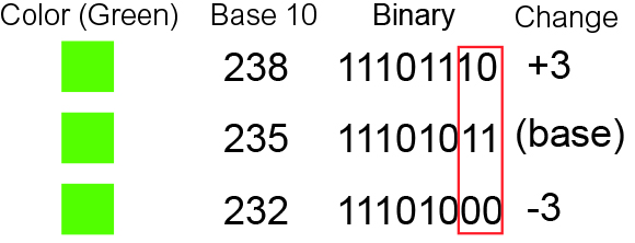
In computing, bit numbering is the convention used to identify the bit positions in a binary number. Bit significance and indexing In computing, the least significant bit (LSb) is the bit position in a binary integer representing the lowest-order place of the integer. Similarly, the most significant bit (MSb) represents the highest-order place of the binary integer. The LSb is sometimes referred to as the ''low-order bit''. Due to the convention in positional notation of writing less significant digits further to the right, the LSb also might be referred to as the ''right-most bit''. The MSb is similarly referred to as the ''high-order bit'' or ''left-most bit''. In both cases, the LSb and MSb correlate directly to the least significant digit and most significant digit of a decimal integer. Bit indexing correlates to the positional notation of the value in base 2. For this reason, bit index is not affected by how the value is stored on the device, such as the value's byte ord ... [...More Info...] [...Related Items...] OR: [Wikipedia] [Google] [Baidu] |
Quantizer
Quantization, in mathematics and digital signal processing, is the process of mapping input values from a large set (often a continuous set) to output values in a (countable) smaller set, often with a finite number of elements. Rounding and truncation are typical examples of quantization processes. Quantization is involved to some degree in nearly all digital signal processing, as the process of representing a signal in digital form ordinarily involves rounding. Quantization also forms the core of essentially all lossy compression algorithms. The difference between an input value and its quantized value (such as round-off error) is referred to as quantization error, noise or distortion. A device or algorithmic function that performs quantization is called a quantizer. An analog-to-digital converter is an example of a quantizer. Example For example, rounding a real number x to the nearest integer value forms a very basic type of quantizer – a ''uniform'' one. A typical ... [...More Info...] [...Related Items...] OR: [Wikipedia] [Google] [Baidu] |
Oversampling
In signal processing, oversampling is the process of sampling (signal processing), sampling a signal at a sampling frequency significantly higher than the Nyquist rate. Theoretically, a bandwidth-limited signal can be perfectly reconstructed if sampled at the Nyquist rate or above it. The Nyquist rate is defined as twice the Bandwidth (signal processing), bandwidth of the signal. Oversampling is capable of improving Resolution (audio), resolution and signal-to-noise ratio, and can be helpful in avoiding aliasing and phase distortion by relaxing anti-aliasing filter performance requirements. A signal is said to be oversampled by a factor of ''N'' if it is sampled at ''N'' times the Nyquist rate. Motivation There are three main reasons for performing oversampling: to improve anti-aliasing performance, to increase resolution and to reduce noise. Anti-aliasing Oversampling can make it easier to realize analog anti-aliasing filters. Without oversampling, it is very difficult to impl ... [...More Info...] [...Related Items...] OR: [Wikipedia] [Google] [Baidu] |
Delta-sigma Modulation
Delta-sigma (ΔΣ; or sigma-delta, ΣΔ) modulation is an oversampling method for encoding signals into low bit depth digital signals at a very high sample-frequency as part of the process of delta-sigma analog-to-digital converters (ADCs) and digital-to-analog converters (DACs). Delta-sigma modulation achieves high quality by utilizing a negative feedback loop during quantization to the lower bit depth that continuously corrects quantization errors and moves quantization noise to higher frequencies well above the original signal's bandwidth. Subsequent low-pass filtering for demodulation easily removes this high frequency noise and time averages to achieve high accuracy in amplitude, which can be ultimately encoded as pulse-code modulation (PCM). Both ADCs and DACs can employ delta-sigma modulation. A delta-sigma ADC (e.g. Figure 1 top) encodes an analog signal using high-frequency delta-sigma modulation and then applies a digital filter to demodulate it t ... [...More Info...] [...Related Items...] OR: [Wikipedia] [Google] [Baidu] |
256-QAM
Quadrature amplitude modulation (QAM) is the name of a family of digital modulation methods and a related family of analog modulation methods widely used in modern telecommunications to transmit information. It conveys two analog message signals, or two digital bit streams, by changing (''modulating'') the amplitudes of two carrier waves, using the amplitude-shift keying (ASK) digital modulation scheme or amplitude modulation (AM) analog modulation scheme. The two carrier waves are of the same frequency and are out of phase with each other by 90°, a condition known as orthogonality or quadrature. The transmitted signal is created by adding the two carrier waves together. At the receiver, the two waves can be coherently separated (demodulated) because of their orthogonality. Another key property is that the modulations are low-frequency/low-bandwidth waveforms compared to the carrier frequency, which is known as the narrowband assumption. Phase modulation (analog PM) and phas ... [...More Info...] [...Related Items...] OR: [Wikipedia] [Google] [Baidu] |
Signal-to-noise And Distortion Ratio
Signal-to-noise and distortion ratio (SNDR) is a term used for a set of measures of the quality of a signal from a communications device. These include SINAD and SINADR. SINAD The signal-to-noise and distortion ratio (SINAD) is a measure of the quality of a signal from a communications device, often defined as : \mathrm = 10\log_ \frac, where P is the average power of the signal, noise and distortion components. The noise power term can include both thermal noise and quantization noise. SINAD is usually expressed in dB and is quoted alongside the receiver RF sensitivity, to give a quantitative evaluation of the receiver sensitivity. Note that with this definition, unlike SNR, a SINAD reading can never be less than 1 (i.e. it is always positive when quoted in dB). When calculating the distortion, it is common to exclude the DC components. Due to widespread use, SINAD has collected several different definitions. SINAD is commonly defined as: #The ratio of (a) total received ... [...More Info...] [...Related Items...] OR: [Wikipedia] [Google] [Baidu] |
Spurious-free Dynamic Range
Spurious-free dynamic range (SFDR) is the strength ratio of the fundamental signal to the strongest spurious signal in the output. It is also defined as a measure used to specify analog-to-digital and digital-to-analog converters (ADCs and DACs, respectively) and radio receivers. SFDR is defined as the ratio of the RMS value of the carrier wave (maximum signal component) at the input of the ADC or output of DAC to the RMS value of the next largest noise or harmonic distortion component (which is referred to as “spurious” or a “spur”) at its output. SFDR is usually measured in dBc (i.e. with respect to the carrier signal amplitude) or in dBFS (i.e. with respect to the ADC's full-scale range). Depending on the test condition, SFDR is observed within a pre-defined frequency window or from DC up to Nyquist frequency of the converter (ADC or DAC). In case of a radio receiver application, the definition is slightly different. The reference is the minimum detectable signal l ... [...More Info...] [...Related Items...] OR: [Wikipedia] [Google] [Baidu] |
Sample And Hold
In electronics, a sample and hold (also known as sample and follow) circuit is an analog device that samples (captures, takes) the voltage of a continuously varying analog signal and holds (locks, freezes) its value at a constant level for a specified minimum period of time. Sample and hold circuits and related peak detectors are the elementary analog memory devices. They are typically used in analog-to-digital converters to eliminate variations in input signal that can corrupt the conversion process.Kefauver and Patschke, p. 37. They are also used in electronic music, for instance to impart a random quality to successively-played notes. A typical sample and hold circuit stores electric charge in a capacitor and contains at least one switching device such as a FET (field effect transistor) switch and normally one operational amplifier.Horowitz and Hill, p. 220. To sample the input signal, the switch connects the capacitor to the output of a buffer amplifier. The buffer ampl ... [...More Info...] [...Related Items...] OR: [Wikipedia] [Google] [Baidu] |


