|
PCB Reverse Engineering
Reverse engineering of Printed circuit boards (sometimes called “cloning”, or PCB RE) is the process of generating fabrication and design data for an existing circuit board, either closely or exactly replicating its functionality. Obtaining circuit board design data is not by necessity malicious or aimed at intellectual property theft. The data generated in the reverse engineering process can be used for troubleshooting, repair, redesign and re-manufacturing, or even testing the security of a device to be used in a restricted environment. Uses Legacy product support Legacy systems need maintenance and replacement parts to operate past their intended life cycle. Demand for parts that are no longer being manufactured can lead to material shortages of parts, called DMS/DMSMS. There is much demand that entire government divisions have been created to regulate and plan the obsolescence of those systems and parts. Areas commonly affected by technical obsolescence include power st ... [...More Info...] [...Related Items...] OR: [Wikipedia] [Google] [Baidu] |
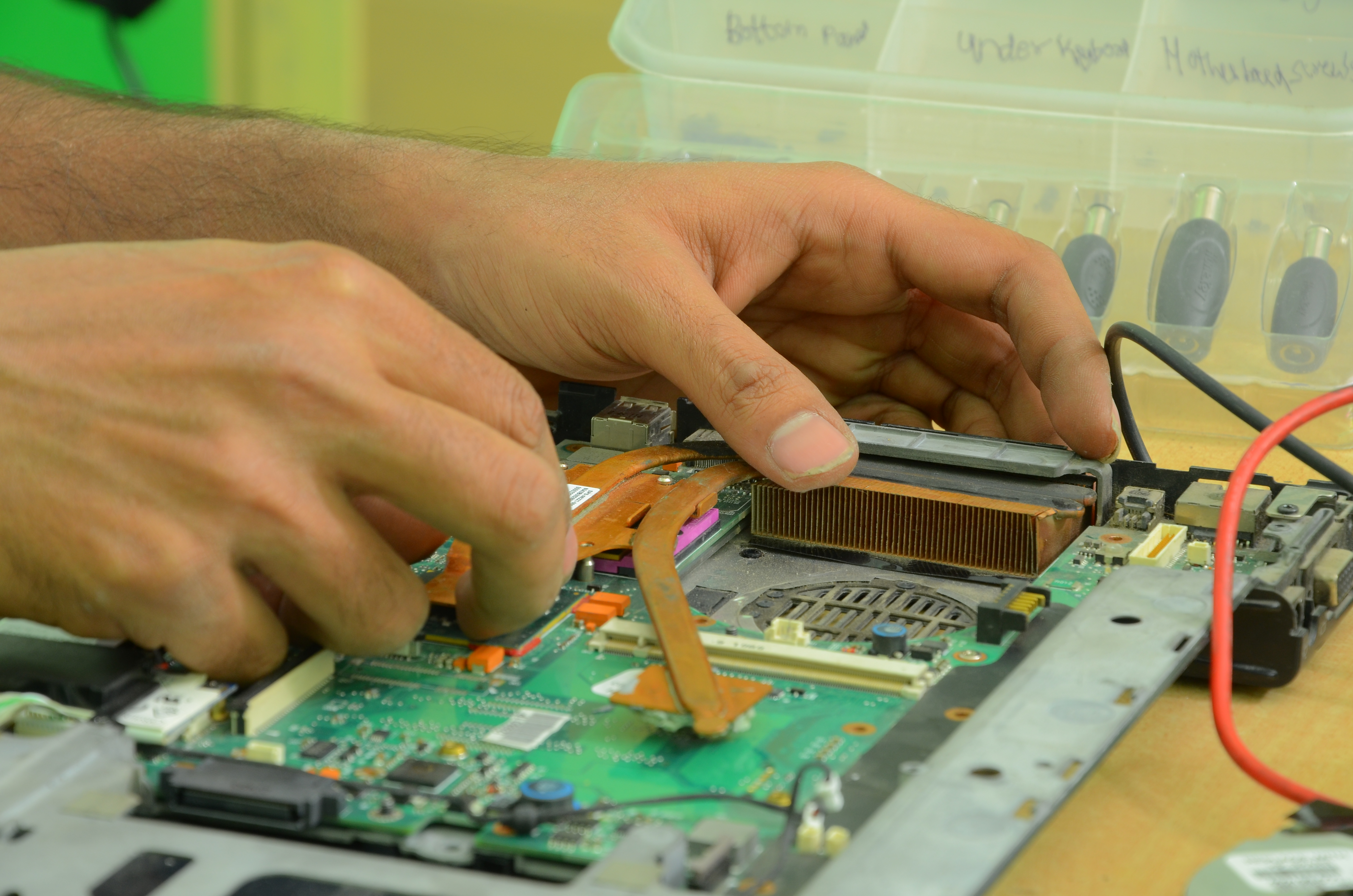
Computer Repair In Progress
A computer is a machine that can be programmed to carry out sequences of arithmetic or logical operations (computation) automatically. Modern digital electronic computers can perform generic sets of operations known as programs. These programs enable computers to perform a wide range of tasks. A computer system is a nominally complete computer that includes the hardware, operating system (main software), and peripheral equipment needed and used for full operation. This term may also refer to a group of computers that are linked and function together, such as a computer network or computer cluster. A broad range of industrial and consumer products use computers as control systems. Simple special-purpose devices like microwave ovens and remote controls are included, as are factory devices like industrial robots and computer-aided design, as well as general-purpose devices like personal computers and mobile devices like smartphones. Computers power the Internet, which links bill ... [...More Info...] [...Related Items...] OR: [Wikipedia] [Google] [Baidu] |
Differential Signaling
Differential signalling is a method for electrically transmitting information using two complementary signals. The technique sends the same electrical signal as a differential pair of signals, each in its own conductor. The pair of conductors can be wires in a twisted-pair or ribbon cable or traces on a printed circuit board. Electrically, the two conductors carry voltage signals which are equal in magnitude, but of opposite polarity. The receiving circuit responds to the difference between the two signals, which results in a signal with a magnitude twice as large. The symmetrical signals of differential signalling may be referred to as ''balanced'', but this term is more appropriately applied to balanced circuits and balanced lines which reject common-mode interference when fed into a differential receiver. Differential signalling does not make a line balanced, nor does noise rejection in balanced circuits require differential signalling. Differential signallin ... [...More Info...] [...Related Items...] OR: [Wikipedia] [Google] [Baidu] |
ASCII
ASCII ( ), abbreviated from American Standard Code for Information Interchange, is a character encoding standard for electronic communication. ASCII codes represent text in computers, telecommunications equipment, and other devices. Because of technical limitations of computer systems at the time it was invented, ASCII has just 128 code points, of which only 95 are , which severely limited its scope. All modern computer systems instead use Unicode, which has millions of code points, but the first 128 of these are the same as the ASCII set. The Internet Assigned Numbers Authority (IANA) prefers the name US-ASCII for this character encoding. ASCII is one of the IEEE milestones. Overview ASCII was developed from telegraph code. Its first commercial use was as a seven-bit teleprinter code promoted by Bell data services. Work on the ASCII standard began in May 1961, with the first meeting of the American Standards Association's (ASA) (now the American National Standards I ... [...More Info...] [...Related Items...] OR: [Wikipedia] [Google] [Baidu] |
PCB NC Formats
PCB NC drill files convey PCB drilling and routing information. The NC formats were originally designed by CNC drill and route machine vendors as proprietary input formats for their equipment, and are known under their company name: Excellon, Hitachi, Sieb & Meyer, Posalux, etc. These formats are similar as they are based on RS-274-C and related to G-code. In 1985 IPC published a generic standard NC format, IPC-NC-349. Later XNC was designed, a simple strict subset of IPC-NC-349, designed not for driving machines but for exchanging drill information between CAD and CAM. They are collectively referred to as (PCB) NC files. The NC files are primarily used to drive CNC machines, and they are adequate for that task. They are also used to exchange design information between CAD and CAM, for which they are ''not'' adequate: essential information such as plating and drill span is missing. Furthermore, the NC output in CAD systems is often poorly implemented, resulting in poor registrati ... [...More Info...] [...Related Items...] OR: [Wikipedia] [Google] [Baidu] |
Stencil
Stencilling produces an image or pattern on a surface, by applying pigment to a surface through an intermediate object, with designed holes in the intermediate object, to create a pattern or image on a surface, by allowing the pigment to reach only some parts of the surface. The stencil is both the resulting image or pattern and the intermediate object; the context in which ''stencil'' is used makes clear which meaning is intended. In practice, the (object) stencil is usually a thin sheet of material, such as paper, plastic, wood or metal, with letters or a design cut from it, used to produce the letters or design on an underlying surface by applying pigment through the cut-out holes in the material. The key advantage of a stencil is that it can be reused to repeatedly and rapidly produce the same letters or design. Although aerosol or painting stencils can be made for one-time use, typically they are made with the intention of being reused. To be reusable, they must remain in ... [...More Info...] [...Related Items...] OR: [Wikipedia] [Google] [Baidu] |
Solder Mask
Solder mask, solder stop mask or solder resist is a thin lacquer-like layer of polymer that is usually applied to the copper traces of a printed circuit board (PCB) for protection against oxidation and to prevent solder bridges from forming between closely spaced solder pads. A solder bridge is an unintended electrical connection between two conductors by means of a small blob of solder. PCBs use solder masks to prevent this from happening. Solder mask is not always used for hand soldered assemblies, but is essential for mass-produced boards that are soldered automatically using reflow or wave soldering techniques. Once applied, openings must be made in the solder mask wherever components are soldered, which is accomplished using photolithography. Solder mask is traditionally green, but is also available in many other colors. Solder mask comes in different media depending upon the demands of the application. The lowest-cost solder mask is epoxy liquid that is silkscreened t ... [...More Info...] [...Related Items...] OR: [Wikipedia] [Google] [Baidu] |
ODB++
ODB++ is a proprietary CAD-to-CAM data exchange format used in the design and manufacture of electronic devices. Its purpose is to exchange printed circuit board design information between design and manufacturing and between design tools from different EDA/ECAD vendors. It was originally developed by Valor Computerized Systems, Ltd. (acquired in 2010 by Mentor Graphics which was later acquired by Siemens in 2016) as the job description format for their CAM system. ODB stands for open database, but its openness is disputed,IPC-2581 Panel: A Spirited Discussion on PCB Data Transfer Formats , Richard Goering, Cadence Design Systems blog, October 2, 2011 on the panel session "Data Transfer in the 21st ... [...More Info...] [...Related Items...] OR: [Wikipedia] [Google] [Baidu] |
Gerber RS-274X
The Gerber format is an open ASCII vector format for printed circuit board (PCB) designs. It is the de facto standard used by PCB industry software to describe the printed circuit board images: copper layers, solder mask, legend, drill data, etc. The official website contains the specification, test files, notes and the Reference Gerber Viewer to support users and especially developers of Gerber software. Gerber is used in PCB fabrication data. PCBs are designed on a specialized electronic design automation (EDA) or a computer-aided design (CAD) system. The CAD systems output PCB fabrication data to allow fabrication of the board. This data typically contains a Gerber file for each image layer (copper layers, solder mask, legend or silk...). Gerber is also the standard image input format for all bare board fabrication equipment needing image data, such as photoplotters, legend printers, direct imagers or automated optical inspection (AOI) machines and for viewing reference im ... [...More Info...] [...Related Items...] OR: [Wikipedia] [Google] [Baidu] |
Pick-and-place Machine
Surface-mount technology (SMT) component placement systems, commonly called pick-and-place machines or P&Ps, are robotic machines which are used to place surface-mount devices (SMDs) onto a printed circuit board (PCB). They are used for high speed, high precision placing of a broad range of electronic components, like capacitors, resistors, integrated circuits onto the PCBs which are in turn used in computers, consumer electronics as well as industrial, medical, automotive, military and telecommunications equipment. Similar equipment exists for through-hole components. This type of equipment is sometimes also used to package microchips using the flip chip method. History 1980s and 1990s During this time, a typical SMT assembly line employed two different types of pick-and-place (P&P) machines arranged in sequence. The unpopulated board was fed into a rapid placement machine. These machines, sometimes called chip shooters, place mainly low-precision, simple package compo ... [...More Info...] [...Related Items...] OR: [Wikipedia] [Google] [Baidu] |
Bill Of Materials
A bill of materials or product structure (sometimes bill of material, BOM or associated list) is a list of the raw materials, sub-assemblies, intermediate assemblies, sub-components, parts, and the quantities of each needed to manufacture an end product. A BOM may be used for communication between manufacturing partners or confined to a single manufacturing plant. A bill of materials is often tied to a production order whose issuance may generate reservations for components in the bill of materials that are in stock and requisitions for components that are not in stock. There are two types of bill materials. A BOM can define products as they are designed (engineering bill of materials), as they are ordered (sales bill of materials), as they are built ( manufacturing bill of materials), or as they are maintained (service bill of materials). The different types depend on the business need and use for which they are intended. In process industries, the BOM is also known as the form ... [...More Info...] [...Related Items...] OR: [Wikipedia] [Google] [Baidu] |
Gerber Format
The Gerber format is an open ASCII vector format for printed circuit board (PCB) designs. It is the de facto standard used by PCB industry software to describe the printed circuit board images: copper layers, solder mask, legend, drill data, etc. The official website contains the specification, test files, notes and the Reference Gerber Viewer to support users and especially developers of Gerber software. Gerber is used in PCB fabrication data. PCBs are designed on a specialized electronic design automation (EDA) or a computer-aided design (CAD) system. The CAD systems output PCB fabrication data to allow fabrication of the board. This data typically contains a Gerber file for each image layer (copper layers, solder mask, legend or silk...). Gerber is also the standard image input format for all bare board fabrication equipment needing image data, such as photoplotters, legend printers, direct imagers or automated optical inspection (AOI) machines and for viewing reference ima ... [...More Info...] [...Related Items...] OR: [Wikipedia] [Google] [Baidu] |


