|
Burst Mode Clock And Data Recovery
The passive optical network (PON) uses tree-like network topology. Due to the topology of PON, the transmission modes for downstream (that is, from optical line termination, (OLT) to optical network unit (ONU)) and upstream (that is, from ONU to OLT) are different. For the downstream transmission, the OLT broadcasts optical signal to all the ONUs in continuous mode (CM), that is, the downstream channel always has optical data signal. One given ONU can find which frame in the CM stream is for it by reading the header of the frame. However, in the upstream channel, ONUs can not transmit optical data signal in CM. It is because that all the signals transmitted from the ONUs converge (with attenuation) into one fiber by the power splitter (serving as power coupler), and overlap among themselves if CM is used. To solve this problem, burst mode (BM) transmission is adopted for upstream channel. The given ONU only transmits optical packet when it is allocated a time slot and it needs to t ... [...More Info...] [...Related Items...] OR: [Wikipedia] [Google] [Baidu] |
Passive Optical Network
A passive optical network (PON) is a fiber-optic telecommunications network that uses only ''unpowered'' devices to carry signals, as opposed to electronic equipment. In practice, PONs are typically used for the '' last mile'' between Internet service providers (ISP) and their customers. In this use, a PON has a point-to-multipoint topology in which an ISP uses a single device to serve many end-user sites using a system such as 10G-PON or GPON. In this one-to-many topology, a single fiber serving many sites branches into multiple fibers through a passive splitter, and those fibers can each serve multiple sites through further splitters. The light from the ISP is divided through the splitters to reach all the customer sites, and light from the customer sites is combined into the single fiber. Many fiber ISPs prefer this system. Components and characteristics A passive optical network consists of an optical line terminal (OLT) at the service provider's central office (hub), p ... [...More Info...] [...Related Items...] OR: [Wikipedia] [Google] [Baidu] |
Optical Line Termination
An optical line termination (OLT), also called an optical line terminal, is a device which serves as the service provider endpoint of a passive optical network. It provides two main functions: # to perform conversion between the electrical signals used by the service provider's equipment and the fiber optic signals used by the passive optical network. # to coordinate the multiplexing between the conversion devices on the other end of that network (called either optical network terminals or optical network units). In general, an OLT is akin to a Network Switch where each port represents one or more client ONT or a node. Each port may be attached to the boards or network/line cards via a SFP module which must be a OLT module for it to have its Tx and Rx wavelengths swapped, but not all OLTs use SFP modules as shown in the image to the left. OLTs are either found at the ISP level inside a cabinet or distribution point, or customer level for connecting ONTs locally, such as a ... [...More Info...] [...Related Items...] OR: [Wikipedia] [Google] [Baidu] |
Optical Network Unit
upTwo simple NIDs, carrying six lines each, on the outside of a building upA German copper phone line termination box called '':de:Abschlusspunkt Linientechnik, Abschlusspunkt LinienTechnik'' (APL, "Demarcation point") In telecommunications, a network interface device (NID; also known by several other names) is a device that serves as the demarcation point between the carrier's local loop and the customer's premises wiring. Outdoor telephone NIDs also provide the subscriber with access to the station wiring and serve as a convenient test point for verification of loop integrity and of the subscriber's inside wiring. Naming Generically, an NID may also be called a network interface unit (NIU), telephone network interface (TNI), system network interface (SNI), or telephone network box. Australia's National Broadband Network uses the term ''network termination device'' or NTD. A smartjack is a type of NID with capabilities beyond simple electrical connection, such as diagnost ... [...More Info...] [...Related Items...] OR: [Wikipedia] [Google] [Baidu] |
Continuous Transmission Mode
Continuous transmission mode is a telecommunications mode where a good part of the communication transmission links are of the continuous-mode type, in which the signal is present at all times. In more quantitative terms, continuous transmission mode takes place: *at constant bit rate, *when the communication channel is active for times much longer than both: **the time needed to set up the channel itself, and/or **the time needed to transmit any file or record or any other sequence of information bearing bits. See also * Burst transmission Burst may refer to: *Burst mode (other), a mode of operation where events occur in rapid succession **Burst transmission, a term in telecommunications **Burst switching, a feature of some packet-switched networks **Bursting, a signaling mo ... References Telecommunications techniques {{telecomm-stub ... [...More Info...] [...Related Items...] OR: [Wikipedia] [Google] [Baidu] |
Time Division Multiple Access
Time-division multiple access (TDMA) is a channel access method for shared-medium networks. It allows several users to share the same frequency channel by dividing the signal into different time slots. The users transmit in rapid succession, one after the other, each using its own time slot. This allows multiple stations to share the same transmission medium (e.g. radio frequency channel) while using only a part of its channel capacity. Dynamic TDMA is a TDMA variant that dynamically reserves a variable number of time slots in each frame to variable bit-rate data streams, based on the traffic demand of each data stream. TDMA is used in digital 2G cellular systems such as Global System for Mobile Communications (GSM), IS-136, Personal Digital Cellular (PDC) and iDEN, in the Maritime Automatic Identification System, and in the Digital Enhanced Cordless Telecommunications (DECT) standard for portable phones. TDMA was first used in satellite communication systems by ... [...More Info...] [...Related Items...] OR: [Wikipedia] [Google] [Baidu] |
Phase-locked Loop
A phase-locked loop or phase lock loop (PLL) is a control system that generates an output signal whose phase is fixed relative to the phase of an input signal. Keeping the input and output phase in lockstep also implies keeping the input and output frequencies the same, thus a phase-locked loop can also track an input frequency. Furthermore, by incorporating a frequency divider, a PLL can generate a stable frequency that is a multiple of the input frequency. These properties are used for clock synchronization, demodulation, frequency synthesis, clock multipliers, and signal recovery from a noisy communication channel. Since 1969, a single integrated circuit can provide a complete PLL building block, and nowadays have output frequencies from a fraction of a hertz up to many gigahertz. Thus, PLLs are widely employed in radio, telecommunications, computers (e.g. to distribute precisely timed clock signals in microprocessors), grid-tie inverters (electronic power converters used ... [...More Info...] [...Related Items...] OR: [Wikipedia] [Google] [Baidu] |
Clock Recovery
Clock recovery is a process in serial communication used to extract timing information from a stream of serial data being sent in order to accurately determine payload sequence without separate clock information. It is widely used in data communications; the similar concept used in analog systems like color television is known as carrier recovery. Basic concept In serial communication data is normally transmitted and received as a series of pulses with well-defined timing constraints. In asynchronous serial communication this presents a problem for the receiving side: if their own clock is not precisely synchronized with the transmitter, they may sample the signal at the wrong time and thereby decode the signal incorrectly. Partially, the problem may be addressed with extremely accurate and stable clocks, like atomic clocks, but these are expensive and complex. More common low-cost clock systems, like quartz oscillators, are accurate enough for this task over short periods of ti ... [...More Info...] [...Related Items...] OR: [Wikipedia] [Google] [Baidu] |
Injection Locked Oscillator
Injection locking and injection pulling are the frequency effects that can occur when a harmonic oscillator is disturbed by a second oscillator operating at a nearby frequency. When the coupling is strong enough and the frequencies near enough, the second oscillator can capture the first oscillator, causing it to have essentially identical frequency as the second oscillator. This is injection locking. When the second oscillator merely disturbs the first but does not capture it, the effect is called injection pulling. Injection locking and pulling effects are observed in numerous types of physical systems, however the terms are most often associated with electronic oscillators or laser resonators. Injection locking has been used in beneficial and clever ways in the design of early television sets and oscilloscopes, allowing the equipment to be synchronized to external signals at a relatively low cost. Injection locking has also been used in high performance frequency doubling circui ... [...More Info...] [...Related Items...] OR: [Wikipedia] [Google] [Baidu] |
Clock Signal
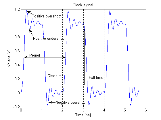
In electronics and especially synchronous digital circuits, a clock signal (historically also known as ''logic beat'') is an electronic logic signal (voltage or current) which oscillates between a high and a low state at a constant frequency and is used like a metronome to synchronize actions of digital circuits. In a synchronous logic circuit, the most common type of digital circuit, the clock signal is applied to all storage devices, flip-flops and latches, and causes them all to change state simultaneously, preventing race conditions. A clock signal is produced by an electronic oscillator called a clock generator. The most common clock signal is in the form of a square wave with a 50% duty cycle. Circuits using the clock signal for synchronization may become active at either the rising edge, falling edge, or, in the case of double data rate, both in the rising and in the falling edges of the clock cycle. Digital circuits Most integrated circuits (ICs) of suffi ... [...More Info...] [...Related Items...] OR: [Wikipedia] [Google] [Baidu] |


