|
Stress Raiser
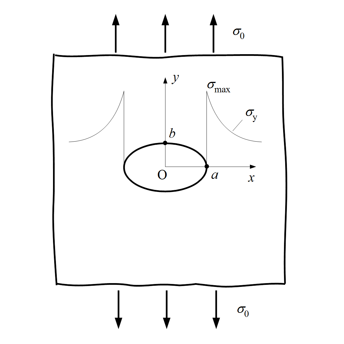
In solid mechanics, a stress concentration (also called a stress raiser or a stress riser or notch sensitivity) is a location in an object where the stress is significantly greater than the surrounding region. Stress concentrations occur when there are irregularities in the geometry or material of a structural component that cause an interruption to the flow of stress. This arises from such details as holes, grooves, notches and fillets. Stress concentrations may also occur from accidental damage such as nicks and scratches. The degree of concentration of a discontinuity under typically tensile loads can be expressed as a non-dimensional stress concentration factor K_t, which is the ratio of the highest stress to the nominal far field stress. For a circular hole in an infinite plate, K_t = 3. The stress concentration factor should not be confused with the stress intensity factor, which is used to define the effect of a crack on the stresses in the region around a crack tip. ... [...More Info...] [...Related Items...] OR: [Wikipedia] [Google] [Baidu] |
Microvoid Coalescence
Microvoid coalescence (MVC) is a high energy microscopic fracture mechanism observed in the majority of metallic alloys and in some engineering plastics. Fracture process MVC proceeds in three stages: nucleation, growth, and coalescence of microvoids. The nucleation of microvoids can be caused by particle cracking or interfacial failure between precipitate particles and the matrix. Additionally, microvoids often form at grain boundaries or inclusions within the material. Microvoids grow during plastic flow of the matrix, and microvoids coalesce when adjacent microvoids link together or the material between microvoids experiences necking. Microvoid coalescence leads to fracture. Void growth rates can be predicted assuming continuum plasticity using the Rice-Tracey model: \ln\left(\frac\right) = \int\limits_^ A\left(\frac\right)d\epsilon_v^p where A is a constant typically equal to 0.283 (but dependent upon the stress triaxiality), \sigma_ is the yield stress, \sigma_m is t ... [...More Info...] [...Related Items...] OR: [Wikipedia] [Google] [Baidu] |
Meshfree Methods
In the field of numerical analysis, meshfree methods are those that do not require connection between nodes of the simulation domain, i.e. a mesh, but are rather based on interaction of each node with all its neighbors. As a consequence, original extensive properties such as mass or kinetic energy are no longer assigned to mesh elements but rather to the single nodes. Meshfree methods enable the simulation of some otherwise difficult types of problems, at the cost of extra computing time and programming effort. The absence of a mesh allows Lagrangian simulations, in which the nodes can move according to the velocity field. Motivation Numerical methods such as the finite difference method, finite-volume method, and finite element method were originally defined on meshes of data points. In such a mesh, each point has a fixed number of predefined neighbors, and this connectivity between neighbors can be used to define mathematical operators like the derivative. These operators ... [...More Info...] [...Related Items...] OR: [Wikipedia] [Google] [Baidu] |
Boundary Element Method
The boundary element method (BEM) is a numerical computational method of solving linear partial differential equations which have been formulated as integral equations (i.e. in ''boundary integral'' form), including fluid mechanics, acoustics, electromagnetics (where the technique is known as method of moments or abbreviated as MoM), fracture mechanics, and contact mechanics. Mathematical basis The integral equation may be regarded as an exact solution of the governing partial differential equation. The boundary element method attempts to use the given boundary conditions to fit boundary values into the integral equation, rather than values throughout the space defined by a partial differential equation. Once this is done, in the post-processing stage, the integral equation can then be used again to calculate numerically the solution directly at any desired point in the interior of the solution domain. BEM is applicable to problems for which Green's functions can be calculated. ... [...More Info...] [...Related Items...] OR: [Wikipedia] [Google] [Baidu] |
Finite Element Method
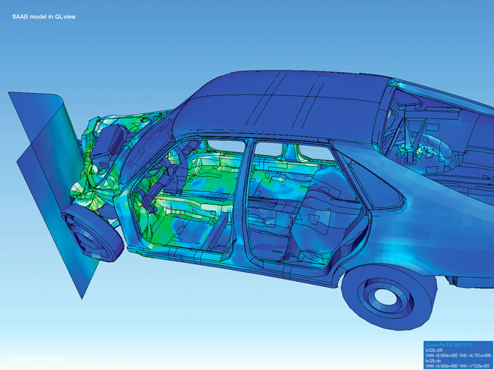
Finite element method (FEM) is a popular method for numerically solving differential equations arising in engineering and mathematical modeling. Typical problem areas of interest include the traditional fields of structural analysis, heat transfer, fluid flow, mass transport, and electromagnetic potential. Computers are usually used to perform the calculations required. With high-speed supercomputers, better solutions can be achieved and are often required to solve the largest and most complex problems. FEM is a general numerical method for solving partial differential equations in two- or three-space variables (i.e., some boundary value problems). There are also studies about using FEM to solve high-dimensional problems. To solve a problem, FEM subdivides a large system into smaller, simpler parts called finite elements. This is achieved by a particular space discretization in the space dimensions, which is implemented by the construction of a mesh of the object: the numer ... [...More Info...] [...Related Items...] OR: [Wikipedia] [Google] [Baidu] |
Strain Gauge
A strain gauge (also spelled strain gage) is a device used to measure Deformation (mechanics)#Strain, strain on an object. Invented by Edward E. Simmons and Arthur C. Ruge in 1938, the most common type of strain gauge consists of an Electrical insulation, insulating flexible backing which supports a metallic foil pattern. The gauge is attached to the object by a suitable adhesive, such as cyanoacrylate. As the object is deformed, the foil is deformed, causing its electrical resistance to change. This resistance change, usually measured using a Wheatstone bridge, is related to the strain by the quantity known as the gauge factor. History Edward E. Simmons and Professor Arthur C. Ruge independently invented the strain gauge. Simmons was involved in a research project by Dätwyler and Clark at Caltech between 1936 and 1938. They researched the stress-strain behavior of metals under shock loads. Simmons came up with an original way to measure the force introduced into the sample b ... [...More Info...] [...Related Items...] OR: [Wikipedia] [Google] [Baidu] |
Photoelasticity
In materials science, photoelasticity describes changes in the optical properties of a material under mechanical deformation. It is a property of all dielectric media and is often used to experimentally determine the stress distribution in a material. History The photoelastic phenomenon was first discovered by the Scottish physicist David Brewster, who immediately recognized it as stress-induced birefringence. That diagnosis was confirmed in a direct refraction experiment by Augustin-Jean Fresnel. * Reprinted in H. de Senarmont, E. Verdet, and L. Fresnel (eds.), ''Oeuvres complètes d'Augustin Fresnel'', vol. 1 (1866)pp. 713–18* Translated as Experimental frameworks were developed at the beginning of the twentieth century with the works of E.G. Coker and L.N.G. Filon of University of London. Their book ''Treatise on Photoelasticity'', published in 1930 by Cambridge Press, became a standard text on the subject. Between 1930 and 1940, many othe ... [...More Info...] [...Related Items...] OR: [Wikipedia] [Google] [Baidu] |
Thermal Stress
In mechanics and thermodynamics, thermal stress is mechanical stress created by any change in temperature Temperature is a physical quantity that quantitatively expresses the attribute of hotness or coldness. Temperature is measurement, measured with a thermometer. It reflects the average kinetic energy of the vibrating and colliding atoms making ... of a material. These stresses can lead to fracturing or plastic deformation depending on the other variables of heating, which include material types and constraints. Temperature gradients, thermal expansion or contraction and thermal shocks are things that can lead to thermal stress. This type of stress is highly dependent on the thermal expansion coefficient which varies from material to material. In general, the greater the temperature change, the higher the level of stress that can occur. Thermal shock can result from a rapid change in temperature, resulting in cracking or shattering. Temperature gradients When a ... [...More Info...] [...Related Items...] OR: [Wikipedia] [Google] [Baidu] |
Ball Bearing
A ball bearing is a type of rolling-element bearing that uses balls to maintain the separation between the bearing races. The purpose of a ball bearing is to reduce rotational friction and support radial and axial loads. It achieves this by using at least two races to contain the balls and transmit the loads through the balls. In most applications, one race is stationary and the other is attached to the rotating assembly (e.g., a hub or shaft). As one of the bearing races rotates it causes the balls to rotate as well. Because the balls are rolling, they have a much lower coefficient of friction than if two flat surfaces were sliding against each other. Ball bearings tend to have lower load capacity for their size than other kinds of rolling-element bearings due to the smaller contact area between the balls and races. However, they can tolerate some misalignment of the inner and outer races. Common ball bearing designs include ''angular contact, axial, deep-groove,'' an ... [...More Info...] [...Related Items...] OR: [Wikipedia] [Google] [Baidu] |
Cam Follower
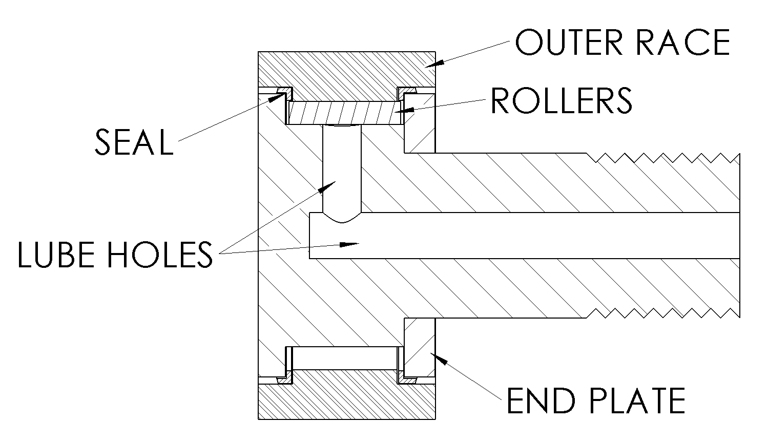
A cam follower, also known as a track follower, is a specialized type of roller or needle bearing designed to follow cam lobe profiles. Cam followers come in a vast array of different configurations, however the most defining characteristic is how the cam follower mounts to its mating part; ''stud'' style cam followers use a stud while the ''yoke'' style has a hole through the middle. Construction The modern stud type follower was invented and patented in 1937 by Thomas L. Robinson of the McGill Manufacturing Company. It replaced using a standard bearing and bolt. The new cam followers were easier to use because the stud was already included and they could also handle higher loads. While roller cam followers are similar to roller bearings, there are quite a few differences. Standard ball and roller bearings are designed to be pressed into a rigid housing, which provides circumferential support. This keeps the outer race from deforming, so the race cross-section is relativel ... [...More Info...] [...Related Items...] OR: [Wikipedia] [Google] [Baidu] |
Radius Of Curvature (applications)
In differential geometry, the radius of curvature, , is the reciprocal of the curvature. For a curve, it equals the radius of the circular arc which best approximates the curve at that point. For surfaces, the radius of curvature is the radius of a circle that best fits a normal section or combinations thereof. Definition In the case of a space curve, the radius of curvature is the length of the curvature vector. In the case of a plane curve, then is the absolute value of : R \equiv \left, \frac \ = \frac, where is the arc length from a fixed point on the curve, is the tangential angle and is the curvature. Formula In two dimensions If the curve is given in Cartesian coordinates as , i.e., as the graph of a function, then the radius of curvature is (assuming the curve is differentiable up to order 2) R =\left, \frac \\,, where y' = \frac\,, y'' = \frac, and denotes the absolute value of . If the curve is given parametrically by functions and , then the radi ... [...More Info...] [...Related Items...] OR: [Wikipedia] [Google] [Baidu] |
Notch (engineering)
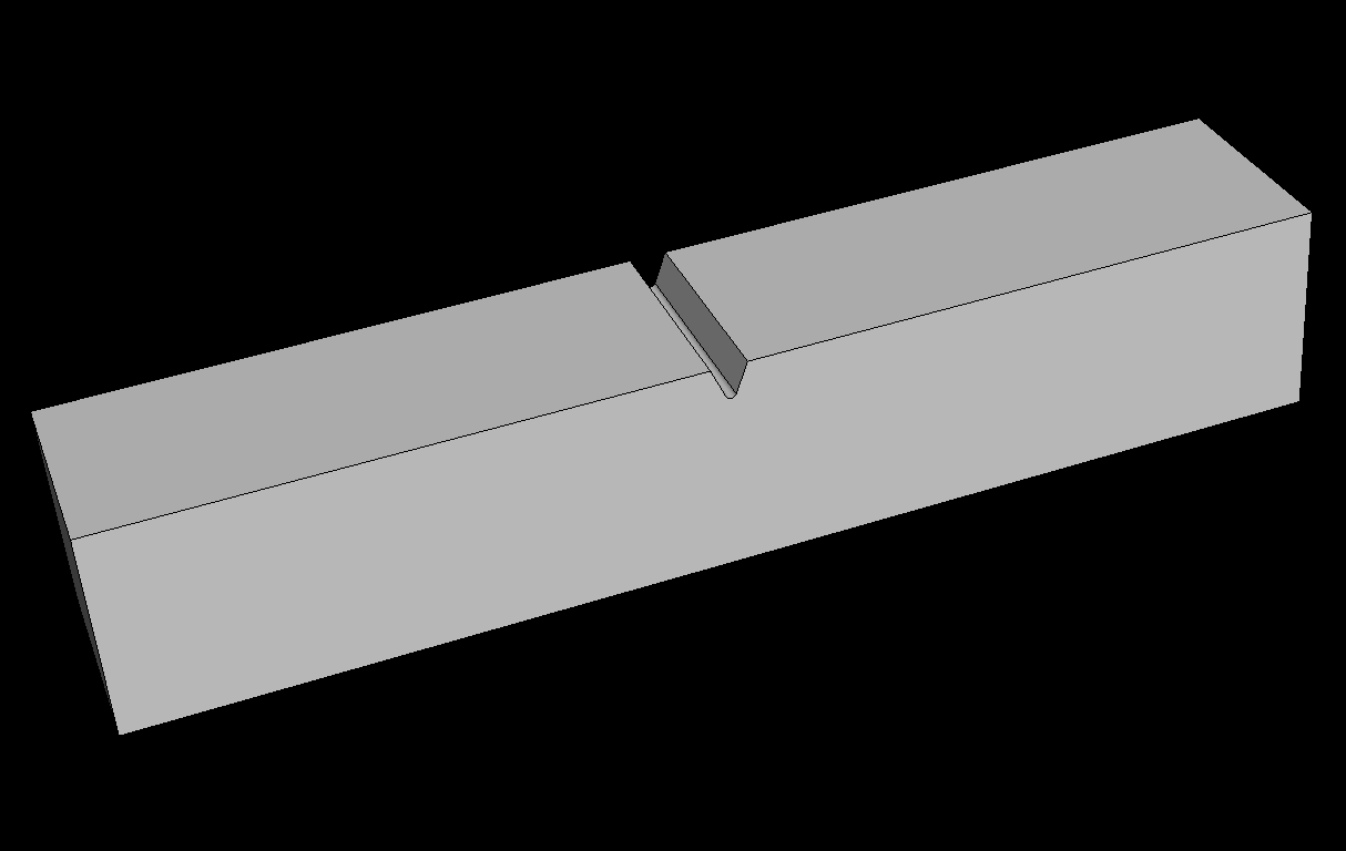
In mechanical engineering and materials science, a notch refers to a V-shaped, U-shaped, or semi-circular defect deliberately introduced into a planar material. In structural components, a notch causes a stress concentration which can result in the initiation and growth of fatigue cracks. Notches are used in materials characterization to determine fracture mechanics related properties such as fracture toughness and rates of fatigue crack growth. Notches are commonly used in material impact tests where a morphological crack of a controlled origin is necessary to achieve standardized characterization of fracture resistance of the material. The most common is the Charpy impact test, which uses a pendulum hammer (striker) to strike a horizontal notched specimen. The height of its subsequent swing-through is used to determine the energy absorbed during fracture. The Izod impact strength test uses a circular notched vertical specimen in a cantilever configuration. Charpy testing is c ... [...More Info...] [...Related Items...] OR: [Wikipedia] [Google] [Baidu] |


