|
Straight Line Linkage
A straight-line mechanism is a Mechanism (engineering), mechanism that converts any type of rotary or angular motion to perfect or near-perfect straight-line motion, or ''vice versa''. Straight-line motion is linear motion of definite length or "stroke", every forward stroke being followed by a return stroke, giving reciprocating motion. The first such mechanism, patented in 1784 by James Watt, produced approximate straight-line motion, referred to by Watt as Watt's linkage, parallel motion. Straight-line mechanisms are used in a variety of applications, such as engines, vehicle suspensions, walking robots, and rover wheels. History In the late eighteenth century, before the development of the Planer (metalworking), planer and the milling machine, it was extremely difficult to machine straight, flat surfaces. During that era, much thought was given to the problem of attaining a straight-line motion, as this would allow the flat surfaces to be machined. To find a solution ... [...More Info...] [...Related Items...] OR: [Wikipedia] [Google] [Baidu] |
Watts Linkage
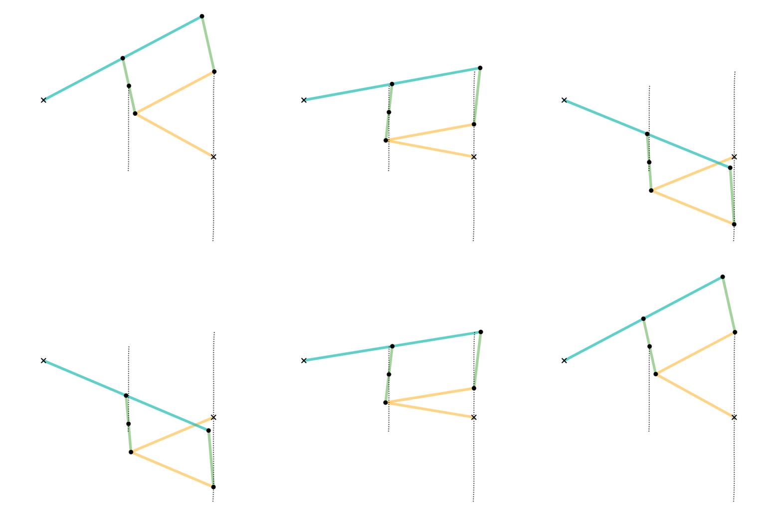
A Watt's linkage is a type of mechanical linkage invented by James Watt in which the central moving point of the linkage is constrained to travel a nearly straight path. Watt's described the linkage in his patent specification of 1784 for the Watt steam engine. Today it is used in automobile suspensions, where it is key to a suspension's kinematics, i.e., its motion properties, constraining the vehicle axle's movement to nearly vertical travel while also limiting horizontal motion. Description Watt's linkage consists of three bars bolted together in a chain. The chain of bars consists of two end bars and a middle bar. The middle bar is bolted at each of its ends to one of the ends of each outer bar. The two outer bars are of equal length, and are longer than the middle bar. The three bars can pivot around the two bolts. The outer endpoints of the long bars are fixed in place relative to each other, but otherwise the three bars are free to pivot around the two joints where t ... [...More Info...] [...Related Items...] OR: [Wikipedia] [Google] [Baidu] |
Chebyshev Linkage
In kinematics, Chebyshev's linkage is a four-bar linkage that converts rotational motion to approximate linear motion. It was invented by the 19th-century mathematician Pafnuty Chebyshev, who studied theoretical problems in kinematic Mechanism (engineering), mechanisms. One of the problems was the construction of a linkage that converts a rotary motion into an approximate straight-line motion (a straight line mechanism). This was also studied by James Watt in his improvements to the steam engine, which resulted in Watt's linkage. – Cross link straight-line mechanism Equations of motion The motion of the linkage can be constrained to an input angle that may be changed through velocities, forces, etc. The input angles can be either link ''L''2 with the horizontal or link ''L ...[...More Info...] [...Related Items...] OR: [Wikipedia] [Google] [Baidu] |
Quadruplanar Inversor
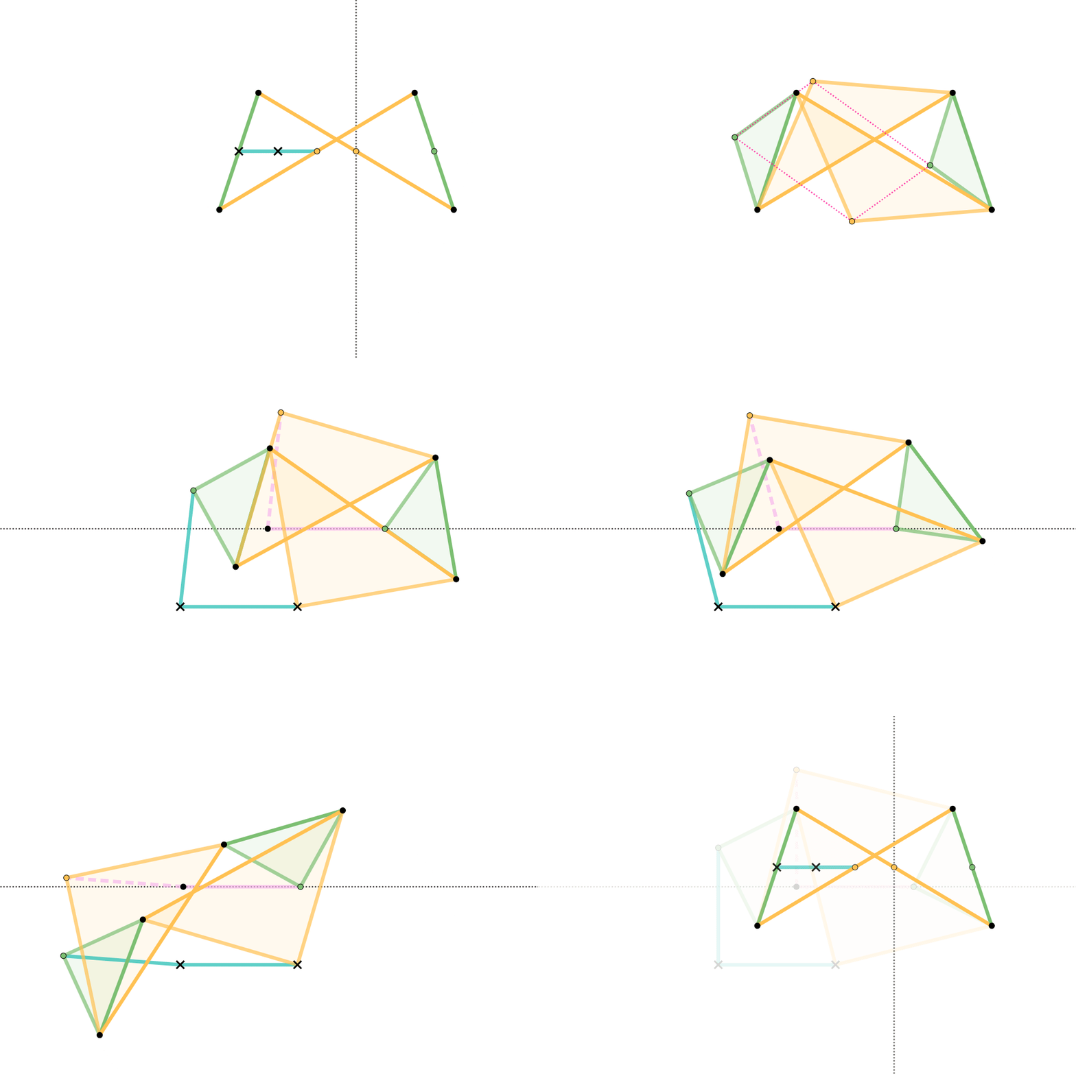
The Quadruplanar inversor of Sylvester and Kempe is a generalization of Hart's inversor. Like Hart's inversor, is a mechanism that provides a perfect straight line motion without sliding guides. The mechanism was described in 1875 by James Joseph Sylvester in the journal Nature (journal), Nature. Like Hart's inversor, it is based on an antiparallelogram but the rather than placing the fixed, input and output points on the sides (dividing them in fixed proportion so they are all similar), Sylvester recognized that the additional points could be displaced sideways off the sides, as long as they formed similar triangles. Hart's original form is simply the degenerate case of triangles with altitude zero. Gallery In these diagrams: * The antiparallelogram is highlighted in full opacity links. * Yellow Triangles and Green Triangles are similar. ** Green Triangles are congruent with each other. ** Yellow Triangles are congruent with each other. * Cyan links and Pink links are congruen ... [...More Info...] [...Related Items...] OR: [Wikipedia] [Google] [Baidu] |
Hart's Inversor
Hart's inversors are two planar mechanisms that provide a perfect straight line motion using only rotary joints. They were invented and published by Harry Hart (mathematician), Harry Hart in 1874–5. Hart's first inversor Hart's first inversor, also known as ''Hart's W-frame'', is based on an antiparallelogram. The addition of fixed points and a driving arm make it a 6-bar linkage. It can be used to convert rotary motion to a perfect straight line by fixing a point on one short link and driving a point on another link in a circular arc. Rectilinear bar and quadruplanar inversors Hart's first inversor is demonstrated as a six-bar linkage with only a single point that travels in a straight line. This can be modified into an eight-bar linkage with a bar that travels in a rectilinear fashion, by taking the ground and input (shown as cyan in the animation), and appending it onto the original output. A further generalization by James Joseph Sylvester and Alfred Kempe extends th ... [...More Info...] [...Related Items...] OR: [Wikipedia] [Google] [Baidu] |
Peaucellier–Lipkin Linkage
The Peaucellier–Lipkin linkage (or Peaucellier–Lipkin cell, or Peaucellier–Lipkin inversor), invented in 1864, was the first true planar straight line mechanism – the first planar linkage capable of transforming rotary motion into perfect straight-line motion, and vice versa. It is named after Charles-Nicolas Peaucellier (1832–1913), a French army officer, and Yom Tov Lipman Lipkin (1846–1876), a Lithuanian Jew and son of the famed Rabbi Israel Salanter. Until this invention, no planar method existed of converting exact straight-line motion to circular motion, without reference guideways. In 1864, all power came from steam engines, which had a piston moving in a straight-line up and down a cylinder. This piston needed to keep a good seal with the cylinder in order to retain the driving medium, and not lose energy efficiency due to leaks. The piston does this by remaining perpendicular to the axis of the cylinder, retaining its straight-line motio ... [...More Info...] [...Related Items...] OR: [Wikipedia] [Google] [Baidu] |
Sarrus Linkage
The Sarrus linkage, invented in 1853 by Pierre Frédéric Sarrus, is a mechanical linkage to convert a limited circular motion to a linear motion or vice versa without reference guideways. It is a spatial six-bar linkage (6R) with two groups of three parallel adjacent joint-axes. Although Charles-Nicolas Peaucellier was widely recognized for being the first to invent such a straight-line mechanism, the Sarrus linkage had been invented earlier; however, it was largely unnoticed for a time. – Sarrus' mechanism Description The Sarrus linkage consists of four links in two identical groups that are perpendicular to each other, with all links having equal lengths. In the examples shown, the linkage uses two horizontal plates (cyan ...[...More Info...] [...Related Items...] OR: [Wikipedia] [Google] [Baidu] |
Inversive Geometry
In geometry, inversive geometry is the study of ''inversion'', a transformation of the Euclidean plane that maps circles or lines to other circles or lines and that preserves the angles between crossing curves. Many difficult problems in geometry become much more tractable when an inversion is applied. Inversion seems to have been discovered by a number of people contemporaneously, including Steiner (1824), Quetelet (1825), Bellavitis (1836), Stubbs and Ingram (1842–3) and Kelvin (1845). The concept of inversion can be generalized to higher-dimensional spaces. Inversion in a circle Inverse of a point To invert a number in arithmetic usually means to take its reciprocal. A closely related idea in geometry is that of "inverting" a point. In the plane, the inverse of a point ''P'' with respect to a ''reference circle (Ø)'' with center ''O'' and radius ''r'' is a point ''P'', lying on the ray from ''O'' through ''P'' such that :OP \cdot OP^ = r^2. This is calle ... [...More Info...] [...Related Items...] OR: [Wikipedia] [Google] [Baidu] |
Hoecken Linkage
In kinematics, the Hoecken linkage (named for Karl Hoecken) is a four-bar linkage that converts rotational motion to approximate straight-line motion. The Hoecken linkage is a cognate linkage of the Chebyshev linkage and Chebyshev's Lambda Mechanism. The linkage was first published in 1926. A generalization of the Hoecken linkage is Wittgenstein's rod. See also *Chebyshev linkage and Chebyshev lambda linkage, linkages that produce a very similar locus without the need of a sliding joint. *Straight line mechanism *Four-bar linkage In the study of Mechanism (engineering), mechanisms, a four-bar linkage, also called a four-bar, is the simplest closed-Kinematic chain, chain movable linkage (mechanical), linkage. It consists of four Rigid body, bodies, called ''bars'' or ''link ... References External links Straight line mechanisms Linkages (mechanical) {{technology-stub ... [...More Info...] [...Related Items...] OR: [Wikipedia] [Google] [Baidu] |
Level Luffing Crane
A level-luffing crane is a crane mechanism where the hook remains at the same level while luffing: moving the jib up and down, so as to move the hook inwards and outwards relative to the base. Usually the description is only applied to those with a luffing jib that have some ''additional'' mechanism applied to keep the hook level when luffing. Level-luffing is most important when careful movement of a load near ground level is required, such as in construction or shipbuilding. This partially explains the popularity of fixed horizontal jibs in these fields. Toplis cable luffing An early form of level-luffing gear was the "Toplis" design, invented by a Stothert & Pitt engineer in 1914. The crane jibs luffs as for a conventional crane, with the end of the jib rising and falling. The crane's hook is kept level by automatically paying out enough extra cable to compensate for this. This is also a purely mechanical linkage, arranged by the reeving of the hoist cables to the jib ... [...More Info...] [...Related Items...] OR: [Wikipedia] [Google] [Baidu] |


