|
KTX Sancheon
The KTX-Sancheon (, formerly called the KTX-II) is a South Korean high-speed train built by Hyundai Rotem and operated by Korail and SR Corporation. With the maximum operational speed of , the KTX-Sancheon is the second commercial high-speed train operated in South Korea, as well as the country's first domestically developed high-speed train in commercial service. The KTX-Sancheon can be divided into four classes: Classes 110000 and 140000 which are owned and operated by Korail, Class 120000 which is owned by Korail but leased to SR Corporation for operation, and Class 130000 which is owned and operated by SR Corporation. History When South Korea started its high-speed rail project, rolling stock and infrastructure was built in the framework of a technology transfer agreement between GEC-Alsthom (today Alstom), the main maker of French TGV high-speed trains, and South Korean companies. Thus Korea Train Express (KTX) began operating with KTX-I trains, which were derived from ... [...More Info...] [...Related Items...] OR: [Wikipedia] [Google] [Baidu] |
Super Rapid Train
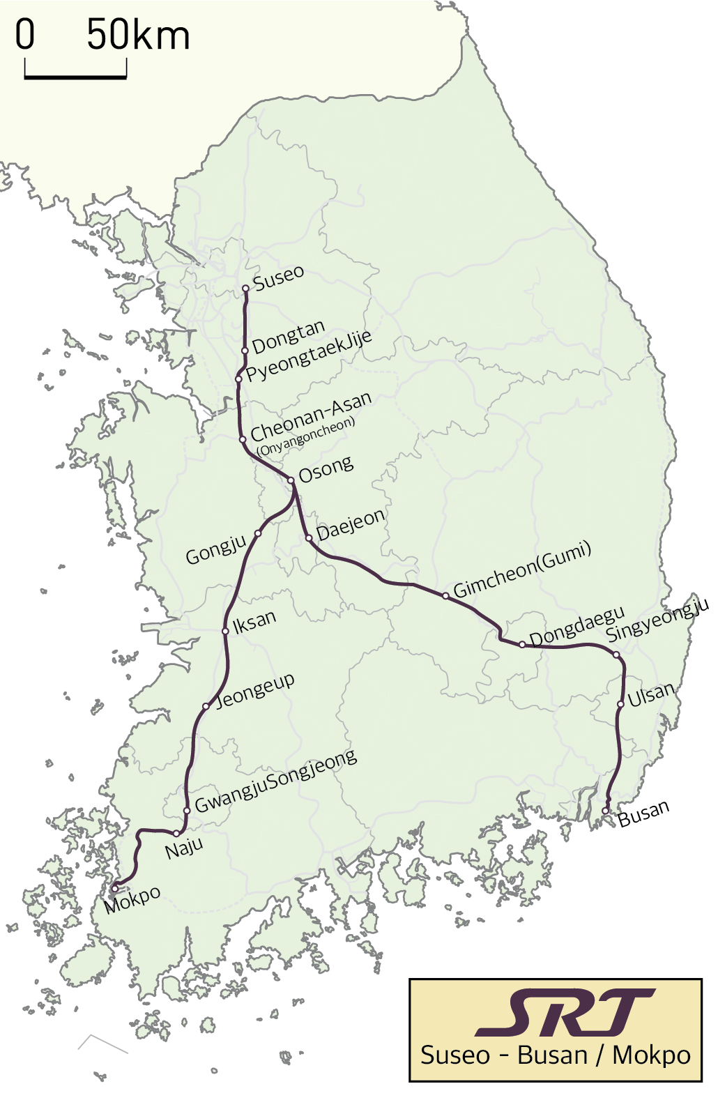
The Super Rapid Train (), often known as SRT, is a high-speed rail service in South Korea operated by SR Corporation. The service starts at Suseo station in southeast Seoul and terminates at either Busan station or Mokpo station. Around 86% of the train service runs 50 meters underground between Suseo and Cheonan-Asan stations. Dongtan station, the first station after departing from Suseo, is the first underground high-speed railway station in Korea. The SRT runs the Seoul–Busan route 8 minutes faster than KTX as it travels exclusively on dedicated Suseo–Pyeongtaek, Gyeongbu and Honam HSR lines. The Suseo-Pyeongtaek HSR line was built exclusively for this service. Branding Before official announcement by SR, Ministry of Land, Infrastructure and Transport used tentative term called ''Suseo High-speed Railway (수서고속철도)''. On October 12, 2015, SR proposed three candidate name for new high-speed rail service – SRT (Super Rapid Train), HSR (High-speed trai ... [...More Info...] [...Related Items...] OR: [Wikipedia] [Google] [Baidu] |
Variable-frequency Drive
A variable-frequency drive (VFD, or adjustable-frequency drive, adjustable-speed drive, variable-speed drive, AC drive, micro drive, inverter drive, variable voltage variable frequency drive, or drive) is a type of AC motor, AC motor drive (system incorporating a motor) that controls speed and torque by varying the frequency of the input electricity. Depending on its Topology (electrical circuits), topology, it controls the associated voltage or electric current, current variation., quote is per definition on p. 4 of NEMA Standards Publication ICS 7.2-2021. VFDs are used in applications ranging from small appliances to large compressors. Systems using VFDs can be more efficient than hydraulics, hydraulic systems, such as in systems with pumps and damper control for fans. Since the 1980s, power electronics technology has reduced VFD cost and size and has improved performance through advances in semiconductor switching devices, drive topologies, simulation and control techniques ... [...More Info...] [...Related Items...] OR: [Wikipedia] [Google] [Baidu] |
Scharfenberg Coupler
The Scharfenberg coupler (, abbreviated ''Schaku'') is a commonly used type of fully automatic railway coupling. Designed in 1903 by Karl Scharfenberg in Königsberg, Germany (today Kaliningrad, Russia), the coupler has gradually spread from transit trains to regular passenger service trains, although outside Europe its use is generally restricted to mass transit systems. The ''Schaku'' is superior in many ways to the Janney coupler, AAR (Janney/knuckle) coupler because it also automates electrical and pneumatic connections and disconnections. However, there is no standard for the placement of these electro-pneumatic connections. Some rail operators have placed them on the sides while others have placed them either below or above the mechanical portion of the coupler. Scharfenberg as a technical design principle and brand name Scharfenberg and the abbreviation Schaku are registered trademarks of Voith Patent GmbH. For this reason, only couplings from Voith can use this name. T ... [...More Info...] [...Related Items...] OR: [Wikipedia] [Google] [Baidu] |
Automatic Train Protection
Automatic train protection (ATP) is the generic term for train protection systems that continually check that the speed of a train is compatible with the permitted speed allowed by signalling, including automatic stop at certain signal aspects. If it is not, ATP activates an Emergency brake (train), emergency brake to stop the train. See also * Advanced Civil Speed Enforcement System * Anti Collision Device * Automatic Warning System * Automatische treinbeïnvloeding (ATB) * Automatic Train Protection (United Kingdom), British Rail's ATP system * Continuous Automatic Warning System (CAWS) * EBICAB * European Train Control System (ETCS) * Kavach_-_Indian_Railways, Kavach * Positive Train Control (PTC) * Punktförmige Zugbeeinflussung (PZB) * Train Protection & Warning System * Train Warning System (India), Train Warning System * Transmission Voie-Machine (TVM) References {{rail-transport-stub Train protection systems ... [...More Info...] [...Related Items...] OR: [Wikipedia] [Google] [Baidu] |
Automatic Train Stop
Automatic train stop or ATS is a system on a train that automatically stops a train if certain situations occur (unresponsive train operator, earthquake, disconnected rail, train running over a stop signal, etc.) to prevent accidents. In some scenarios it functions as a type of dead man's switch. Automatic train stop differs from the concept of Automatic Train Control in that ATS usually does not feature an onboard speed control mechanism. Overview Mechanical systems The invention of the fail-safe railway air brake provided an external means for stopping a train via a physical object opening a valve on the brake line to the atmosphere. Eventually known as ''train stops'' or ''trip stops'', the first mechanical ATS system was installed in France in 1878 with some railroads in Russia following suit using a similar system in 1880. In 1901 Union Switch and Signal Company developed the first North American automatic train stop system for the Boston Elevated Railway. This system was s ... [...More Info...] [...Related Items...] OR: [Wikipedia] [Google] [Baidu] |
Railway Air Brake
A railway air brake is a railway brake power braking system with compressed air as the operating medium. Modern trains rely upon a fail-safe air brake system that is based upon a design patented by George Westinghouse on April 13, 1869. The Westinghouse Air Brake Company was subsequently organized to manufacture and sell Westinghouse's invention. In various forms, it has been nearly universally adopted. The Westinghouse system uses air pressure to charge air reservoirs (tanks) on each car. Full air pressure causes each car to release the brakes. A subsequent reduction or loss of air pressure causes each car to apply its brakes, using the compressed air stored in its reservoirs. Overview Straight air brake In the air brake's simplest form, referred to as a ''straight air system'', compressed air is directed to a ''brake cylinder'', causing its piston to apply force to mechanical linkage, which linkage is conventionally referred to as the ''brake rigging'' (see illu ... [...More Info...] [...Related Items...] OR: [Wikipedia] [Google] [Baidu] |
Disc Brake
A disc brake is a type of brake that uses the #Calipers, calipers to squeeze pairs of #Brake pads, pads against a disc (sometimes called a [brake] rotor) to create friction. There are two basic types of brake pad friction mechanisms: abrasive friction and adherent friction. This action slows the rotation of a shaft, such as a vehicle axle, either to reduce its rotational speed or to hold it stationary. The energy of motion is converted into heat, which must be dissipated to the environment. Hydraulic brakes, Hydraulically Actuator, actuated disc brakes are the most commonly used mechanical device for slowing motor vehicles. The principles of a disc brake apply to almost any rotating shaft. The components include the disc, master cylinder, and caliper, which contain at least one cylinder and two Brake pad, brake pads on both sides of the rotating disc. Design The development of disc-type brakes began in England in the 1890s. In 1902, the Lanchester Motor Company designed bra ... [...More Info...] [...Related Items...] OR: [Wikipedia] [Google] [Baidu] |
Rheostatic Brake
Dynamic braking is the use of an electric traction motor as a generator when slowing a vehicle such as an electric or diesel-electric locomotive. It is termed " rheostatic" if the generated electrical power is dissipated as heat in brake grid resistors, and " regenerative" if the power is returned to the supply line. Dynamic braking reduces wear on friction-based braking components, and regeneration lowers net energy consumption. Dynamic braking may also be used on railcars with multiple units, light rail vehicles, electric trams, trolleybuses, and electric and hybrid electric automobiles. Principle of operation Converting electrical energy to the mechanical energy of a rotating shaft (electric motor) is the inverse of converting the mechanical energy of a rotating shaft to electrical energy (electric generator). Both are accomplished through the interactions of armature windings with a (relatively) moving external magnetic field, with the armature connected to an electrical c ... [...More Info...] [...Related Items...] OR: [Wikipedia] [Google] [Baidu] |
Regenerative Brake
Regenerative braking is an energy recovery mechanism that slows down a moving vehicle or object by converting its kinetic energy or potential energy into a form that can be either used immediately or stored until needed. Typically, regenerative brakes work by driving an electric motor in reverse to recapture energy that would otherwise be lost as heat during braking, effectively turning the traction motor into a generator. Feeding power backwards through the system like this allows the energy harvested from deceleration to resupply an energy storage solution such as a battery or a capacitor. Once stored, this power can then be later used to aid forward propulsion. Because of the electrified vehicle architecture required for such a braking system, automotive regenerative brakes are most commonly found on hybrid and electric vehicles. This method contrasts with conventional braking systems, where excess kinetic energy is converted to unwanted and wasted heat due to friction ... [...More Info...] [...Related Items...] OR: [Wikipedia] [Google] [Baidu] |
Electronically Controlled Pneumatic Brakes
Electronically controlled pneumatic brakes are a type of railway braking systems. Overview Traditional train braking systems use pneumatic valves to control and generate brake applications on the cars along the length of the train. In general, this conventional system consists of a brake pipe that runs the length of the train which supplies air to reservoirs mounted on each of the cars. When the brake pipe and car components are charged with air, the brakes release. When the engineer needs to make a brake application, control valves in the locomotive reduce the brake pipe pressure. As the brake pipe pressure is reduced, the service portions on each car divert air from their reservoirs to their brake cylinders. To release the brakes, the engineer charges the brake pipe. This method of controlling the brakes on freight and passenger cars has remained virtually unchanged since its invention by George Westinghouse in 1868. The conventional braking system suffers from many weakness ... [...More Info...] [...Related Items...] OR: [Wikipedia] [Google] [Baidu] |
Pantograph (rail)
A pantograph (or "pan" or "panto") is an apparatus mounted on the roof of an electric train, tram or trolley buses to collect power through contact with an overhead line. The term stems from the resemblance of some styles to the mechanical pantographs used for copying handwriting and drawings. The pantograph is a common type of current collector; typically, a single or double wire is used, with the return current running through the rails. Other types of current collectors include the bow collector and the trolley pole. Invention The pantograph, with a low-friction, replaceable graphite contact strip or "shoe" to minimise lateral stress on the contact wire, first appeared in the late 19th century. Early versions include the bow collector, invented in 1889 by Walter Reichel, chief engineer at Siemens & Halske in Germany, and a flat slide-pantograph first used in 1895 by the Baltimore and Ohio Railroad. The familiar diamond-shaped roller pantograph was devised and p ... [...More Info...] [...Related Items...] OR: [Wikipedia] [Google] [Baidu] |


