|
DC-balanced
In signal processing, when describing a periodic function in the time domain, the DC bias, DC component, DC offset, or DC coefficient is the mean value of the waveform. A waveform with zero mean or no DC bias is known as a ''DC balanced'' or ''DC free'' waveform. Origin The term originates in electronics, where ''DC'' refers to a direct current voltage. In contrast, various other non-DC frequencies are analogous to superimposed alternating current (AC) voltages or currents, hence called AC component or AC coefficients. Applications In the design of electronic amplifier circuits, every active device has biasing to set its '' operating point'', the steady state current and voltage on the device when no signal is applied. In bipolar transistor biasing, for example, a network of resistors is used to apply a small amount of DC to the base terminal of the transistor. The AC signal is applied at the same terminal and is amplified. The bias network is designed to preserve the applied ... [...More Info...] [...Related Items...] OR: [Wikipedia] [Google] [Baidu] |
Capacitive Coupling
Capacitive coupling (electronics), coupling is the transfer of energy within an electrical network or between distant networks by means of displacement current between circuit(s) node (circuits) , nodes, induced by the electric field. This coupling can have an intentional or accidental effect. In its simplest implementation, capacitive coupling is achieved by placing a capacitor between two nodes. Where analysis of many points in a circuit is carried out, the capacitance at each point and between points can be described in a Capacitance#Capacitance matrix, matrix form. Use in analog circuits In analog circuits, a coupling capacitor is used to connect two circuits such that only the alternating current, AC signal from the first circuit can pass through to the next while direct current, DC is blocked. This technique helps to isolate the DC bias settings of the two coupled circuits. Capacitive coupling is also known as ''AC coupling'' and the capacitor used for the purpose is ... [...More Info...] [...Related Items...] OR: [Wikipedia] [Google] [Baidu] |
Line Code
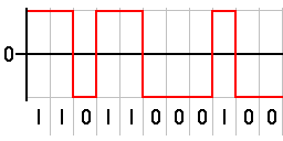
In telecommunications, a line code is a pattern of voltage, current, or photons used to represent digital data transmission (telecommunications), transmitted down a communication channel or written to a storage medium. This repertoire of signals is usually called a constrained code in data storage systems. Some signals are more prone to error than others as the physics of the communication channel or storage medium constrains the repertoire of signals that can be used reliably. Common line encodings are Unipolar encoding, unipolar, Polar encoding, polar, Bipolar encoding, bipolar, and Manchester code. Transmission and storage After line coding, the signal is put through a physical communication channel, either a transmission medium or data storage medium.Karl Paulsen"Coding for Magnetic Storage Mediums".2007. The most common physical channels are: * the line-coded signal can directly be put on a transmission line, in the form of variations of the voltage or current (often us ... [...More Info...] [...Related Items...] OR: [Wikipedia] [Google] [Baidu] |
Signal Processing
Signal processing is an electrical engineering subfield that focuses on analyzing, modifying and synthesizing ''signals'', such as audio signal processing, sound, image processing, images, Scalar potential, potential fields, Seismic tomography, seismic signals, Altimeter, altimetry processing, and scientific measurements. Signal processing techniques are used to optimize transmissions, Data storage, digital storage efficiency, correcting distorted signals, improve subjective video quality, and to detect or pinpoint components of interest in a measured signal. History According to Alan V. Oppenheim and Ronald W. Schafer, the principles of signal processing can be found in the classical numerical analysis techniques of the 17th century. They further state that the digital refinement of these techniques can be found in the digital control systems of the 1940s and 1950s. In 1948, Claude Shannon wrote the influential paper "A Mathematical Theory of Communication" which was publis ... [...More Info...] [...Related Items...] OR: [Wikipedia] [Google] [Baidu] |
Series And Parallel Circuits
Two-terminal components and electrical networks can be connected in series or parallel. The resulting electrical network will have two terminals, and itself can participate in a series or parallel topology. Whether a two-terminal "object" is an electrical component (e.g. a resistor) or an electrical network (e.g. resistors in series) is a matter of perspective. This article will use "component" to refer to a two-terminal "object" that participates in the series/parallel networks. Components connected in series are connected along a single "electrical path", and each component has the same electric current through it, equal to the current through the network. The voltage across the network is equal to the sum of the voltages across each component. Components connected in parallel are connected along multiple paths, and each component has the same voltage across it, equal to the voltage across the network. The current through the network is equal to the sum of the currents thr ... [...More Info...] [...Related Items...] OR: [Wikipedia] [Google] [Baidu] |
Carrier Wave
In telecommunications, a carrier wave, carrier signal, or just carrier, is a periodic waveform (usually sinusoidal) that conveys information through a process called ''modulation''. One or more of the wave's properties, such as amplitude or frequency, are modified by an information bearing signal, called the ''message signal'' or ''modulation signal''. The carrier frequency is usually much higher than the message signal frequency; this is because it is usually impractical to transmit signals with low frequencies over long distances (due to attenuation). The purpose of the carrier is usually either to transmit the information through space as an electromagnetic wave (as in radio communication), or to allow several carriers at different frequencies to share a common physical transmission medium by frequency division multiplexing (as in a cable television system). The term originated in radio communication, where the carrier wave creates the waves which carry the information (mod ... [...More Info...] [...Related Items...] OR: [Wikipedia] [Google] [Baidu] |
Center Frequency
In electrical engineering and telecommunications, the center frequency of a filter or channel is a measure of a central frequency between the upper and lower cutoff frequencies. It is usually defined as either the arithmetic mean or the geometric mean of the lower cutoff frequency and the upper cutoff frequency of a band-pass system or a band-stop system. Typically, the geometric mean is used in systems based on certain transformations of lowpass filter designs, where the frequency response is constructed to be symmetric on a logarithmic frequency scale. The geometric center frequency corresponds to a mapping of the DC response of the prototype lowpass filter, which is a resonant frequency sometimes equal to the peak frequency of such systems, for example as in a Butterworth filter. The arithmetic definition is used in more general situations, such as in describing passband telecommunication systems, where filters are not necessarily symmetric but are treated on a linear fr ... [...More Info...] [...Related Items...] OR: [Wikipedia] [Google] [Baidu] |
Radio Transmitter
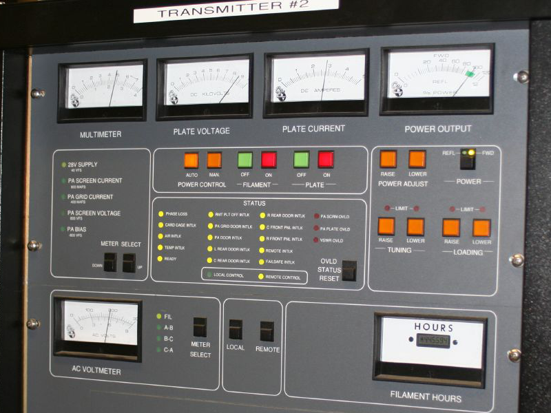
In electronics and telecommunications, a radio transmitter or just transmitter (often abbreviated as XMTR or TX in technical documents) is an electronic device which produces radio waves with an antenna with the purpose of signal transmission to a radio receiver. The transmitter itself generates a radio frequency alternating current, which is applied to the antenna. When excited by this alternating current, the antenna radiates radio waves. Transmitters are necessary component parts of all electronic devices that communicate by radio, such as radio (audio) and television broadcasting stations, cell phones, walkie-talkies, wireless computer networks, Bluetooth enabled devices, garage door openers, two-way radios in aircraft, ships, spacecraft, radar sets and navigational beacons. The term ''transmitter'' is usually limited to equipment that generates radio waves for communication purposes; or radiolocation, such as radar and navigational transmitters. Generators of radio ... [...More Info...] [...Related Items...] OR: [Wikipedia] [Google] [Baidu] |
Voltage-controlled Oscillator
A voltage-controlled oscillator (VCO) is an electronic oscillator whose oscillation frequency is controlled by a voltage input. The applied input voltage determines the instantaneous oscillation frequency. Consequently, a VCO can be used for frequency modulation (FM) or phase modulation (PM) by applying a modulation, modulating signal to the control input. A VCO is also an integral part of a phase-locked loop. VCOs are used in synthesizers to generate a waveform whose Pitch (music), pitch can be adjusted by a voltage determined by a musical keyboard or other input. A voltage-to-frequency converter (VFC) is a special type of VCO designed to be very linear in frequency control over a wide range of input control voltages. Types VCOs can be generally categorized into two groups based on the type of waveform produced. * ''Linear'' or ''harmonic oscillators'' generate a sinusoidal waveform. Harmonic oscillators in electronics usually consist of a resonator with an amplifier that re ... [...More Info...] [...Related Items...] OR: [Wikipedia] [Google] [Baidu] |
Power Amplifier
An audio power amplifier (or power amp) amplifies low-power electronic audio signals, such as the signal from a radio receiver or an electric guitar pickup, to a level that is high enough for driving loudspeakers or headphones. Audio power amplifiers are found in all manner of sound systems including sound reinforcement, public address, home audio systems and musical instrument amplifiers like guitar amplifiers. It is the final electronic stage in a typical audio playback chain before the signal is sent to the loudspeakers. The preceding stages in such a chain are low-power audio amplifiers which perform tasks like pre-amplification of the signal, equalization, mixing different input signals. The inputs can also be any number of audio sources like record players, CD players, digital audio players and cassette players. Most audio power amplifiers require these low-level inputs, which are line level. While the input signal to an audio power amplifier, such as the si ... [...More Info...] [...Related Items...] OR: [Wikipedia] [Google] [Baidu] |
Tape Bias
Tape bias is the term for two techniques, AC bias and DC bias, that improve the fidelity of analogue tape recorders. DC bias is the addition of direct current to the audio signal that is being recorded. AC bias is the addition of an inaudible high-frequency signal (generally from 40 to 150 kHz) to the audio signal. Most contemporary tape recorders use AC bias. When recording, magnetic tape has a nonlinear response as determined by its coercivity. Without bias, this response results in poor performance, especially at low signal levels. A recording signal that generates a magnetic field strength less than the tape's coercivity cannot magnetise the tape and produces little playback signal. Bias increases the signal quality of most audio recordings significantly by pushing the signal into more linear zones of the tape's magnetic transfer function. History Magnetic recording was proposed as early as 1878 by Oberlin Smith, who on 4 October 1878 filed, with the U.S. pa ... [...More Info...] [...Related Items...] OR: [Wikipedia] [Google] [Baidu] |
Audio Recording
Sound recording and reproduction is the electrical, mechanical, electronic, or digital inscription and re-creation of sound waves, such as spoken voice, singing, instrumental music, or sound effects. The two main classes of sound recording technology are analog recording and digital recording. Acoustic analog recording is achieved by a microphone diaphragm that senses changes in atmospheric pressure caused by acoustic sound waves and records them as a mechanical representation of the sound waves on a medium such as a phonograph record (in which a stylus cuts grooves on a record). In magnetic tape recording, the sound waves vibrate the microphone diaphragm and are converted into a varying electric current, which is then converted to a varying magnetic field by an electromagnet, which makes a representation of the sound as magnetized areas on a plastic tape with a magnetic coating on it. Analog sound reproduction is the reverse process, with a larger loudspeaker diaphragm c ... [...More Info...] [...Related Items...] OR: [Wikipedia] [Google] [Baidu] |


