|
Continuity Tester
A continuity tester is an item of electrical test equipment used to determine if an electrical path can be established between two points; that is if an electrical circuit can be made. The circuit under test is completely de-energized prior to connecting the apparatus. Details The tester consists of an indicator in series with a source of electrical power - normally a battery, terminating in two test leads. If a complete circuit is established between the test-leads, the indicator is activated. The indicator may be an electric light or a buzzer. This led to the term "buzzing out a circuit" (which means to test for continuity) Audible continuity buzzers or beepers are built into some models of multimeter, and the continuity setting is normally shared with the ohmmeter setting. A popular design has the tester combined with a standard flashlight. A phone connector or jack plug in the rear of the unit permits a set of test leads to be plugged in effecting a quick conversion betwe ... [...More Info...] [...Related Items...] OR: [Wikipedia] [Google] [Baidu] |
Electrical Resistance
The electrical resistance of an object is a measure of its opposition to the flow of electric current. Its reciprocal quantity is , measuring the ease with which an electric current passes. Electrical resistance shares some conceptual parallels with mechanical friction. The SI unit of electrical resistance is the ohm (), while electrical conductance is measured in siemens (S) (formerly called the 'mho' and then represented by ). The resistance of an object depends in large part on the material it is made of. Objects made of electrical insulators like rubber tend to have very high resistance and low conductance, while objects made of electrical conductors like metals tend to have very low resistance and high conductance. This relationship is quantified by resistivity or conductivity. The nature of a material is not the only factor in resistance and conductance, however; it also depends on the size and shape of an object because these properties are extensive rather than i ... [...More Info...] [...Related Items...] OR: [Wikipedia] [Google] [Baidu] |
Test Light
A test light, test lamp, voltage tester, or mains tester is a piece of electronic test equipment used to determine the presence of electricity in a piece of equipment under test. A test light is simpler and less costly than a measuring instrument such as a multimeter, and often suffices for checking for the presence of voltage on a conductor. Properly designed test lights include features to protect the user from accidental electric shock. Non-contact test lights can detect voltage on insulated conductors. Two-contact test lights The test light is an electric lamp connected with one or two insulated wire leads.Terrel Croft, Wilford Summers ''American Electricians' Handbook, Eleventh Edition'', McGraw Hill, 1987 pages 1-56 through 1-57 Often, it takes the form of a screwdriver with the lamp connected between the tip of the screwdriver and a single lead that projects out the back of the screwdriver. By connecting the flying lead to an earth (ground) reference and touching th ... [...More Info...] [...Related Items...] OR: [Wikipedia] [Google] [Baidu] |
Solenoid Voltmeter
A solenoid voltmeter is a specific type of voltmeter electricians use to test electrical power circuits. It uses a solenoid coil to attract a spring-loaded plunger; the movement of the plunger is calibrated in terms of approximate voltage. It is more rugged than a D'arsonval movement, but neither as sensitive nor as precise. Wiggy is the registered trademark for a common solenoid voltmeter used in North America derived from a device patent assigned to the Wigginton Company, US patent number 1,538,906."Official Gazette of the United States Patent Office", Vol. 334, Government Printing Office, May 1925, pages xxviii, xxxii, xxxix, and 850 Operation Rather than using a D'Arsonval movement or digital electronics, the solenoid voltmeter simply uses a spring-loaded solenoid carrying a pointer (it might also be described as a form of moving iron meter). Greater voltage creates more magnetism pulling the solenoid's core in further against the spring loading, moving the pointer. A ... [...More Info...] [...Related Items...] OR: [Wikipedia] [Google] [Baidu] |
LED Circuit
In electronics, an LED circuit or LED driver is an electrical circuit used to power a light-emitting diode (LED). The circuit must provide sufficient current to light the LED at the required brightness, but must limit the current to prevent damaging the LED. The voltage drop across an LED is approximately constant over a wide range of operating current; therefore, a small increase in applied voltage greatly increases the current. Very simple circuits are used for low-power indicator LEDs. More complex, current source circuits are required when driving high-power LEDs for illumination to achieve correct current regulation. Basic circuit The simplest circuit to drive an LED is through a series resistor. It is commonly used for indicators and digital displays in many consumer appliances. However, this circuit is not energy-efficient, because energy is dissipated in the resistor as heat. An LED has a voltage drop specified at the intended operating current. Ohm's law and Kirchho ... [...More Info...] [...Related Items...] OR: [Wikipedia] [Google] [Baidu] |
Continuity Test
In electronics, a continuity test is the checking of an electric circuit to see if current flows (that it is in fact a complete circuit). A continuity test is performed by placing a small voltage (wired in series with an LED or noise-producing component such as a piezoelectric speaker) across the chosen path. If electron flow is inhibited by broken conductors, damaged components, or excessive resistance, the circuit is "open". Devices that can be used to perform continuity tests include multimeters which measure current and specialized continuity tester A continuity tester is an item of electrical test equipment used to determine if an electrical path can be established between two points; that is if an electrical circuit can be made. The circuit under test is completely de-energized prior to co ...s which are cheaper, more basic devices, generally with a simple light bulb that lights up when current flows. Usage A continuity test can be used to test switches, fuses, el ... [...More Info...] [...Related Items...] OR: [Wikipedia] [Google] [Baidu] |
Cable Tester
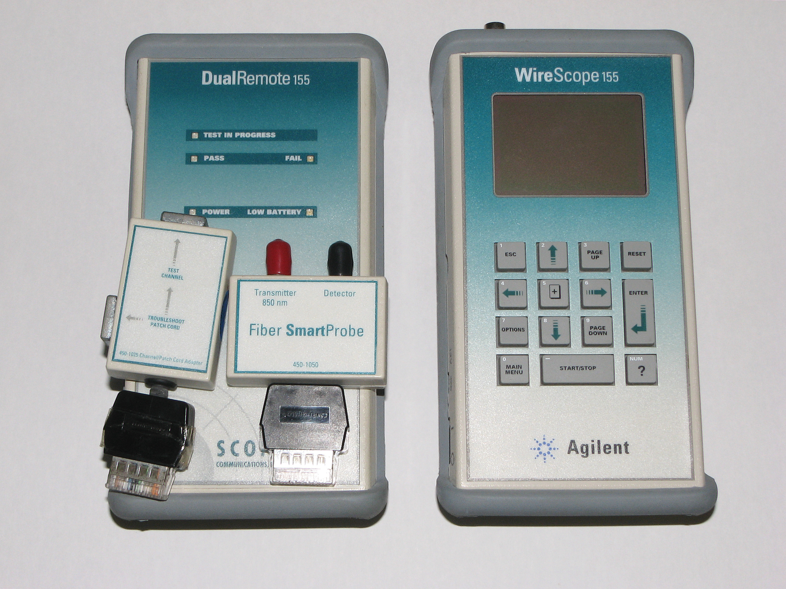
A cable tester is an electronic device used to verify the electrical connections in a signal cable or other wired assembly. Basic cable testers are continuity testers that verify the existence of a conductive path between ends of the cable, and verify the correct wiring of connectors on the cable. More advanced cable testers can measure the signal transmission properties of the cable such as its resistance, signal attenuation, noise and interference.Terry William Ogletree, ''Upgrading and Repairing Networks'', Que Publishing 2004, , page 961 Basic tester Generally a basic cable tester is a battery operated portable instrument with a source of electric current, one or more voltage indicators, and possibly a switching or scanning arrangement to check each of several conductors sequentially. A cable tester may also have a microcontroller and a display to automate the testing process and show the testing results, especially for multiple-conductor cables. A cable tester may be con ... [...More Info...] [...Related Items...] OR: [Wikipedia] [Google] [Baidu] |
Multivibrator
A multivibrator is an electronic circuit used to implement a variety of simple two-state devices such as relaxation oscillators, timers, and flip-flops. The first multivibrator circuit, the astable multivibrator oscillator, was invented by Henri Abraham and Eugene Bloch during World War I. It consisted of two vacuum tube amplifiers cross-coupled by a resistor-capacitor network. They called their circuit a "multivibrator" because its output waveform was rich in harmonics. A variety of active devices can be used to implement multivibrators that produce similar harmonic-rich wave forms; these include transistors, neon lamps, tunnel diodes and others. Although cross-coupled devices are a common form, single-element multivibrator oscillators are also common. The three types of multivibrator circuits are: * Astable multivibrator, in which the circuit is not stable in either state —it continually switches from one state to the other. It functions as a relaxation oscillator. * Monost ... [...More Info...] [...Related Items...] OR: [Wikipedia] [Google] [Baidu] |
Schmitt Trigger
In electronics, a Schmitt trigger is a comparator circuit with hysteresis implemented by applying positive feedback to the noninverting input of a comparator or differential amplifier. It is an active circuit which converts an analog input signal to a digital output signal. The circuit is named a ''trigger'' because the output retains its value until the input changes sufficiently to trigger a change. In the non-inverting configuration, when the input is higher than a chosen threshold, the output is high. When the input is below a different (lower) chosen threshold the output is low, and when the input is between the two levels the output retains its value. This dual threshold action is called '' hysteresis'' and implies that the Schmitt trigger possesses memory and can act as a bistable multivibrator (latch or flip-flop). There is a close relation between the two kinds of circuits: a Schmitt trigger can be converted into a latch and a latch can be converted into a Schmitt ... [...More Info...] [...Related Items...] OR: [Wikipedia] [Google] [Baidu] |
Op-amp
An operational amplifier (often op amp or opamp) is a DC-coupled high- gain electronic voltage amplifier with a differential input and, usually, a single-ended output. In this configuration, an op amp produces an output potential (relative to circuit ground) that is typically 100,000 times larger than the potential difference between its input terminals. The operational amplifier traces its origin and name to analog computers, where they were used to perform mathematical operations in linear, non-linear, and frequency-dependent circuits. The popularity of the op amp as a building block in analog circuits is due to its versatility. By using negative feedback, the characteristics of an op-amp circuit, its gain, input and output impedance, bandwidth etc. are determined by external components and have little dependence on temperature coefficients or engineering tolerance in the op amp itself. Op amps are used widely in electronic devices today, including a vast array of ... [...More Info...] [...Related Items...] OR: [Wikipedia] [Google] [Baidu] |
Phone Connector (audio)
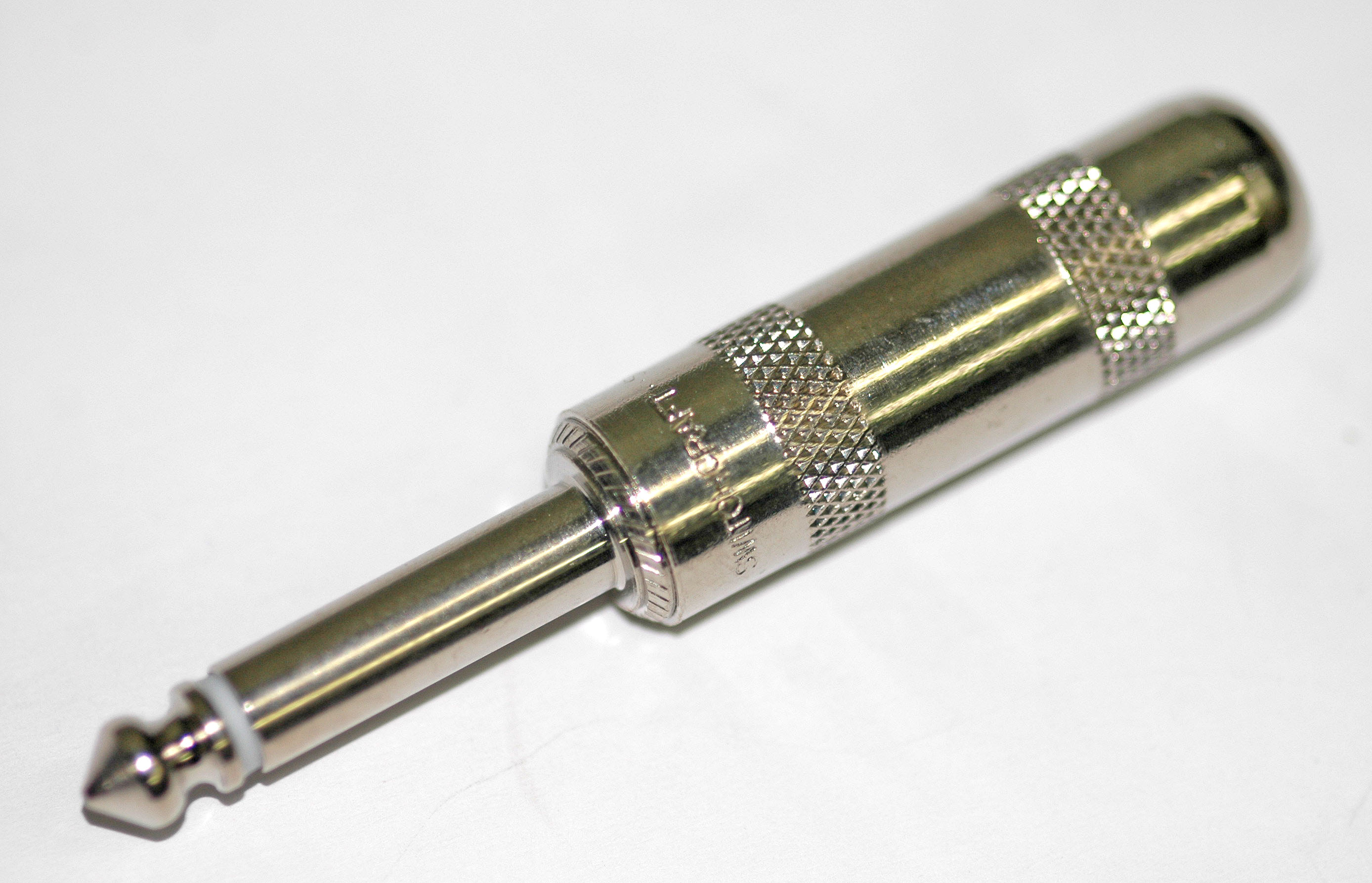
A phone connector, also known as phone jack, audio jack, headphone jack or jack plug, is a family of electrical connectors typically used for analog signal, analog audio signals. A plug, the Gender of connectors and fasteners, male connector, is inserted into the jack, the female connector. The phone connector was invented for use in telephone switchboards in the 19th century and is still widely used. The phone connector is cylindrical in shape, with a grooved tip to retain it. In its original audio configuration, it typically has two, three, four or, occasionally, five contacts. Three-contact versions are known as ''TRS connectors'', where ''T'' stands for Tip and ring, "tip", ''R'' stands for Tip and ring, "ring" and ''S'' stands for "sleeve". Ring contacts are typically the same diameter as the sleeve, the long shank. Similarly, two-, four- and five-contact versions are called ''TS'', ''TRRS'' and ''TRRRS connectors'' respectively. The outside diameter of the "sleeve" c ... [...More Info...] [...Related Items...] OR: [Wikipedia] [Google] [Baidu] |
Electronic Test Equipment
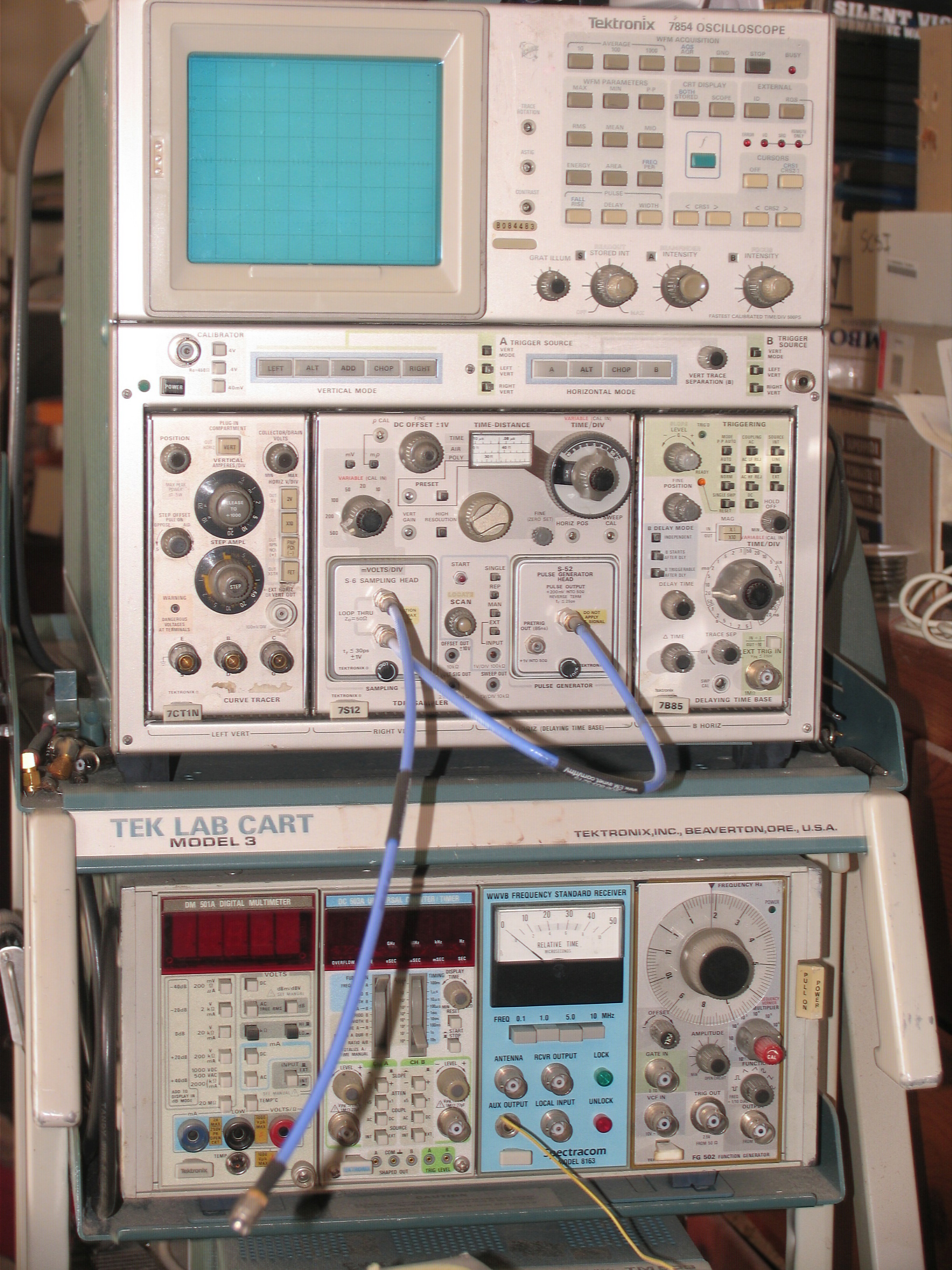
Electronic test equipment is used to create signals and capture responses from electronic devices under test (DUTs). In this way, the proper operation of the DUT can be proven or faults in the device can be traced. Use of electronic test equipment is essential to any serious work on electronics systems. Practical electronics engineering and assembly requires the use of many different kinds of electronic test equipment ranging from the very simple and inexpensive (such as a test light consisting of just a light bulb and a test lead) to extremely complex and sophisticated such as automatic test equipment (ATE). ATE often includes many of these instruments in real and simulated forms. Generally, more advanced test gear is necessary when developing circuits and systems than is needed when doing production testing or when troubleshooting existing production units in the field. Types of test equipment Basic equipment The following items are used for basic measurement of voltages, c ... [...More Info...] [...Related Items...] OR: [Wikipedia] [Google] [Baidu] |


