|
Common-source
In electronics, a common-source amplifier is one of three basic single-stage field-effect transistor (FET) amplifier topologies, typically used as a voltage or transconductance amplifier. The easiest way to tell if a FET is common source, common drain, or common gate is to examine where the signal enters and leaves. The remaining terminal is what is known as "common". In this example, the signal enters the gate, and exits the drain. The only terminal remaining is the source. This is a common-source FET circuit. The analogous bipolar junction transistor circuit may be viewed as a transconductance amplifier or as a voltage amplifier. (See classification of amplifiers). As a transconductance amplifier, the input voltage is seen as modulating the current going to the load. As a voltage amplifier, input voltage modulates the current flowing through the FET, changing the voltage across the output resistance according to Ohm's law. However, the FET device's output resistance typical ... [...More Info...] [...Related Items...] OR: [Wikipedia] [Google] [Baidu] |
Cascode
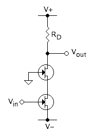
The cascode is a two-stage amplifier that consists of a common-emitter stage feeding into a common-base stage. Compared to a single amplifier stage, this combination may have one or more of the following characteristics: higher input–output isolation, higher input impedance, high output impedance, higher bandwidth. In modern circuits, the cascode is often constructed from two transistors ( BJTs or FETs), with one operating as a common emitter or common source and the other as a common base or common gate. The cascode improves input–output isolation (reduces reverse transmission), as there is no direct coupling from the output to input. This eliminates the Miller effect and thus contributes to a much higher bandwidth. History The use of a cascode (sometimes verbified to ''cascoding'') is a common technique for improving analog circuit performance, applicable to both vacuum tubes and transistors. The name "cascode" was coined in an article written by Frederick Vinton ... [...More Info...] [...Related Items...] OR: [Wikipedia] [Google] [Baidu] |
Common Gate
In electronics, a common-gate amplifier is one of three basic single-stage field-effect transistor (FET) amplifier topologies, typically used as a current buffer or voltage amplifier. In this circuit, the source terminal of the transistor serves as the input, the drain is the output, and the gate is connected to ground, or "common," hence its name. The analogous bipolar junction transistor circuit is the common-base amplifier. Applications This configuration is used less often than the common source or source follower. It is useful in, for example, CMOS RF receivers, especially when operating near the frequency limitations of the FETs; it is desirable because of the ease of impedance matching and potentially has lower noise. Gray and Meyer provide a general reference for this circuit. Low-frequency characteristics At low frequencies and under small-signal conditions, the circuit in Figure 1 can be represented by that in Figure 2, where the hybrid-pi model for the MOSFET ... [...More Info...] [...Related Items...] OR: [Wikipedia] [Google] [Baidu] |
Common Emitter
In electronics, a common-emitter amplifier is one of three basic single-stage bipolar-junction-transistor (BJT) amplifier topologies, typically used as a voltage amplifier. It offers high current gain (typically 200), medium input resistance and a high output resistance. The output of a common emitter amplifier is 180 degrees out of phase to the input signal. In this circuit the base terminal of the transistor serves as the input, the collector is the output, and the emitter is ''common'' to both (for example, it may be tied to ground reference or a power supply rail), hence its name. The analogous FET circuit is the common-source amplifier, and the analogous tube circuit is the common-cathode amplifier. Emitter degeneration Common-emitter amplifiers give the amplifier an inverted output and can have a very high gain that may vary widely from one transistor to the next. The gain is a strong function of both temperature and bias current, and so the actual gain is somewha ... [...More Info...] [...Related Items...] OR: [Wikipedia] [Google] [Baidu] |
Active Load
An active load or dynamic load is a component or a circuit that functions as a current-stable nonlinear resistor. Circuit design In circuit design, an active load is a circuit component made up of ''active devices'', such as transistors, intended to present a high small-signal impedance yet not requiring a large DC voltage drop, as would occur if a large resistor were used instead. Such large AC load impedances may be desirable, for example, to increase the AC gain of some types of amplifier. Most commonly the active load is the output part of a current mirror and is represented in an idealized manner as a current source. Usually, it is only a ''constant-current resistor'' that is a part of the whole current source including a ''constant voltage source'' as well (the power supply ''VCC'' on the figures below). Common base example In Figure 1 the load is a resistor, and the current through the resistor is determined by Ohm's law as: :I_C = \frac {R_C}. As a consequence of th ... [...More Info...] [...Related Items...] OR: [Wikipedia] [Google] [Baidu] |
Small-signal Common Source With C Gd
Small-signal modeling is a common analysis technique in electronics engineering used to approximate the behavior of electronic circuits containing nonlinear devices with linear equations. It is applicable to electronic circuits in which the AC signals (i.e., the time-varying currents and voltages in the circuit) are small relative to the DC bias currents and voltages. A small-signal model is an AC equivalent circuit in which the nonlinear circuit elements are replaced by linear elements whose values are given by the first-order (linear) approximation of their characteristic curve near the bias point. Overview Many of the electrical components used in simple electric circuits, such as resistors, inductors, and capacitors are linear. Circuits made with these components, called linear circuits, are governed by linear differential equations, and can be solved easily with powerful mathematical frequency domain methods such as the Laplace transform. In contrast, many of the com ... [...More Info...] [...Related Items...] OR: [Wikipedia] [Google] [Baidu] |
Miller Effect
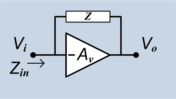
In electronics, the Miller effect accounts for the increase in the equivalent input capacitance of an inverting voltage amplifier due to amplification of the effect of capacitance between the input and output terminals. The virtually increased input capacitance due to the Miller effect is given by :C_=C (1+A_v)\, where -A_v is the voltage gain of the inverting amplifier (A_v positive) and C is the feedback capacitance. Although the term ''Miller effect'' normally refers to capacitance, any impedance connected between the input and another node exhibiting gain can modify the amplifier input impedance via this effect. These properties of the Miller effect are generalized in the Miller theorem. The Miller capacitance due to parasitic capacitance between the output and input of active devices like transistors and vacuum tubes is a major factor limiting their gain at high frequencies. Miller capacitance was identified in 1920 in triode vacuum tubes by John Milton Miller. History ... [...More Info...] [...Related Items...] OR: [Wikipedia] [Google] [Baidu] |
N-channel JFET Common Source
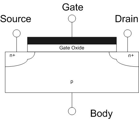
The field-effect transistor (FET) is a type of transistor that uses an electric field to control the flow of current in a semiconductor. FETs (JFETs or MOSFETs) are devices with three terminals: ''source'', ''gate'', and ''drain''. FETs control the flow of current by the application of a voltage to the gate, which in turn alters the conductivity between the drain and source. FETs are also known as unipolar transistors since they involve single-carrier-type operation. That is, FETs use either electrons (n-channel) or holes (p-channel) as charge carriers in their operation, but not both. Many different types of field effect transistors exist. Field effect transistors generally display very high input impedance at low frequencies. The most widely used field-effect transistor is the MOSFET (metal-oxide-semiconductor field-effect transistor). History The concept of a field-effect transistor (FET) was first patented by Austro-Hungarian physicist Julius Edgar Lilienfeld in 1925 ... [...More Info...] [...Related Items...] OR: [Wikipedia] [Google] [Baidu] |
Thévenin's Theorem
As originally stated in terms of direct-current resistive circuits only, Thévenin's theorem states that ''"For any linear electrical network containing only voltage sources, current sources and resistances can be replaced at terminals A–B by an equivalent combination of a voltage source Vth in a series connection with a resistance Rth."'' * The equivalent voltage ''V''th is the voltage obtained at terminals A–B of the network with terminals A–B open circuited. * The equivalent resistance ''R''th is the resistance that the circuit between terminals A and B would have if all ideal voltage sources in the circuit were replaced by a short circuit and all ideal current sources were replaced by an open circuit. * If terminals A and B are connected to one another, the current flowing from A to B will be ''V''th/''R''th. This means that ''R''th could alternatively be calculated as ''V''th divided by the short-circuit current between A and B when they are connected together. ... [...More Info...] [...Related Items...] OR: [Wikipedia] [Google] [Baidu] |
Output Impedance
The output impedance of an electrical network is the measure of the opposition to current flow (impedance), both static (resistance) and dynamic ( reactance), into the load network being connected that is ''internal'' to the electrical source. The output impedance is a measure of the source's propensity to drop in voltage when the load draws current, the source network being the portion of the network that transmits and the load network being the portion of the network that consumes. Because of this the output impedance is sometimes referred to as the source impedance or internal impedance. Description All devices and connections have non-zero resistance and reactance, and therefore no device can be a perfect source. The output impedance is often used to model the source's response to current flow. Some portion of the device's measured output impedance may not physically exist within the device; some are artifacts that are due to the chemical, thermodynamic, or mechanical prope ... [...More Info...] [...Related Items...] OR: [Wikipedia] [Google] [Baidu] |
Parasitic Capacitance
Parasitic capacitance is an unavoidable and usually unwanted capacitance that exists between the parts of an electronic component or circuit simply because of their proximity to each other. When two electrical conductors at different voltages are close together, the electric field between them causes electric charge to be stored on them; this effect is capacitance. All practical circuit elements such as inductors, diodes, and transistors have internal capacitance, which can cause their behavior to depart from that of ideal circuit elements. Additionally, there is always non-zero capacitance between any two conductors; this can be significant with closely spaced conductors, such as wires or printed circuit board traces. The parasitic capacitance between the turns of an inductor or other wound component is often described as ''self-capacitance''. However, in electromagnetics, the term self-capacitance more correctly refers to a different phenomenon: the capacitance of a ... [...More Info...] [...Related Items...] OR: [Wikipedia] [Google] [Baidu] |


