|
4-4-6
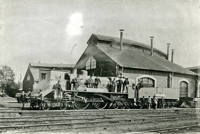
A 4-4-6, in the Whyte notation for the classification of steam locomotives by wheel arrangement, is a locomotive with: * four (4) leading wheels (at the front of the locomotive) * four (4) driving wheels (2 axles) fixed in a rigid frame, and * six (6) trailing wheels (normally mounted in a trailing truck). Usage United States The Providence, Warren and Bristol railroad's No. 4 ''Annawamscutt'' was the only example of a 4-4-6 in the United States. It was rebuilt into a 0-4-4T in 1891. France The only example of this wheel arrangement in France was the Thuile locomotive. Other equivalent classifications are: * UIC classification: 2B3 (also known as German classification * Italian classification), and * French classification Under the French classification system for locomotive wheel arrangements, the system is slightly different for steam and electric/diesel vehicles. Steam The French system counts axles, rather than wheels. As with Whyte notation, a conventional r ...: ... [...More Info...] [...Related Items...] OR: [Wikipedia] [Google] [Baidu] |
Whyte Notation
The Whyte notation is a classification method for steam locomotives, and some internal combustion locomotives and electric locomotives, by wheel arrangement. It was devised by Frederick Methvan Whyte, and came into use in the early twentieth century following a December 1900 editorial in ''American Engineer and Railroad Journal''. The notation was adopted and remains in use in North America and the United Kingdom to describe the wheel arrangements of steam locomotives, but for modern locomotives, multiple units and trams it has been supplanted by the UIC system in Europe and by the AAR system (essentially a simplification of the UIC system) in North America. However, geared steam locomotives do not use the notation. They are classified by their model and their number of trucks. Structure of the system Basic form The notation in its basic form counts the number of leading wheels, then the number of driving wheels, and finally the number of trailing wheels, numbers ... [...More Info...] [...Related Items...] OR: [Wikipedia] [Google] [Baidu] |
Thuile Locomotive
The Thuile locomotive was a steam locomotive designed by M. Henri Thuile, of Alexandria, Egypt, and built in 1899. History Thuile proposed a 6-4-8 or 6-4-6 locomotive with 3-metre-diameter () driving wheels, but it was not built. The design was taken up by Schneider, of Le Creusot, who built a 4-4-6 with 2.5-metre-diameter () driving wheels, and a forward cab for the driver. The two-cylinder locomotive had Walschaerts valve gear and a double-lobed boiler of nickel-steel. The locomotive was exhibited at the International Exposition in Paris in 1900, and the trials were undertaken on the Chemin de Fer de l'Etat line between Chartres and Thouars Thouars () is a commune in the Deux-Sèvres department in western France. On 1 January 2019, the former communes Mauzé-Thouarsais, Missé and Sainte-Radegonde were merged into Thouars. It is on the River Thouet. Its inhabitants are known .... A speed of was attained hauling a load of . The trials ended when Thuile was kille ... [...More Info...] [...Related Items...] OR: [Wikipedia] [Google] [Baidu] |
Wheel Arrangement
In rail transport, a wheel arrangement or wheel configuration is a system of classifying the way in which wheels are distributed under a locomotive. Several notations exist to describe the wheel assemblies of a locomotive by type, position, and connections, with the adopted notations varying by country. Within a given country, different notations may also be employed for different kinds of locomotives, such as steam, electric, and diesel powered. Especially in steam days, wheel arrangement was an important attribute of a locomotive because there were many different types of layout adopted, each wheel being optimised for a different use (often with only some being actually "driven"). Modern diesel and electric locomotives are much more uniform, usually with all axles driven. Major notation schemes The main notations are the Whyte notation (based on counting the wheels), the AAR wheel arrangement notation (based on counting either the axles or the bogies), and the UIC classifi ... [...More Info...] [...Related Items...] OR: [Wikipedia] [Google] [Baidu] |
Trailing Wheel
On a steam locomotive, a trailing wheel or trailing axle is generally an unpowered wheel or axle (Wheelset (rail transport), wheelset) located behind the driving wheels. The axle of the trailing wheels is usually located in a trailing Bogie, truck. On some large locomotives, a booster engine was mounted on the trailing truck to provide extra tractive effort when starting a heavy train and at low speeds on gradients. Trailing wheels were used in some early locomotives but fell out of favor for a time during the latter 19th century. As demand for more powerful locomotives increased, trailing wheels began to be used to support the crew cab and rear firebox area. Trailing wheels first appeared on American locomotives between 1890 and 1895, but their axle worked in rigid pedestals. It enabled boilers to be lowered, since the top of the main frames was dropped down behind the driving wheels and under the firebox. The firebox could also be longer and wider, increasing the heating su ... [...More Info...] [...Related Items...] OR: [Wikipedia] [Google] [Baidu] |
Leading Wheel
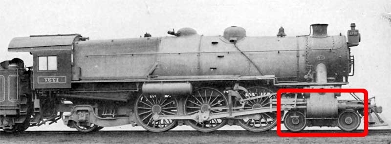
The leading wheel or leading axle or pilot wheel of a steam locomotive is an unpowered wheel or axle located in front of the driving wheels. The axle or axles of the leading wheels are normally located on a leading truck. Leading wheels are used to help the locomotive negotiate curves and to support the front portion of the boiler. Overview Many leading bogies do not have simple rotational motion about a vertical pivot. Bogies with a sliding motion controlled by springs was patented by William Adams in 1865. Other designs used swing links to take the weight of the bogie with a centering action. The first use of leading wheels is commonly attributed to John B. Jervis, who employed them in his 1832 design for a locomotive with four leading wheels and two driving wheels (a type that became known as the ''Jervis''). In the Whyte system of describing locomotive wheel arrangements, his locomotive would be classified as a 4-2-0, that is to say, it had four leading wheels, two dri ... [...More Info...] [...Related Items...] OR: [Wikipedia] [Google] [Baidu] |
Steam Locomotive
A steam locomotive is a locomotive that provides the force to move itself and other vehicles by means of the expansion of steam. It is fuelled by burning combustible material (usually coal, Fuel oil, oil or, rarely, Wood fuel, wood) to heat water in the locomotive's Boiler (power generation), boiler to the point where it becomes gaseous and its volume increases 1,700 times. Functionally, it is a steam engine on wheels. In most locomotives, the steam is admitted alternately to each end of its Steam locomotive components, cylinders in which pistons are mechanically connected to the locomotive's main wheels. Fuel and water supplies are usually carried with the locomotive, either on the locomotive itself or in a Tender (rail), tender coupled to it. #Variations, Variations in this general design include electrically powered boilers, turbines in place of pistons, and using steam generated externally. Steam locomotives were first developed in the United Kingdom of Great Britain an ... [...More Info...] [...Related Items...] OR: [Wikipedia] [Google] [Baidu] |
Driving Wheel
On a steam locomotive, a driving wheel is a powered wheel which is driven by the locomotive's pistons (or turbine, in the case of a steam turbine locomotive). On a conventional, non-articulated locomotive, the driving wheels are all coupled together with side rods (also known as coupling rods); normally one pair is directly driven by the main rod (or connecting rod) which is connected to the end of the piston rod; power is transmitted to the others through the side rods. On diesel and electric locomotives, the driving wheels may be directly driven by the traction motors. Coupling rods are not usually used, and it is quite common for each axle to have its own motor. Jackshaft drive and coupling rods were used in the past (e.g. in the Swiss Crocodile locomotive) but their use is now confined to shunter locomotives. On an articulated locomotive or a duplex locomotive, driving wheels are grouped into sets with wheels within each set linked together. Diameter Drivin ... [...More Info...] [...Related Items...] OR: [Wikipedia] [Google] [Baidu] |
UIC Classification
The UIC classification of locomotive axle arrangements, sometimes known as the German classification''The Railway Data File''. Leicester: Silverdale, 2000. p. 52. . or German system,Kalla-Bishop P.M. & Greggio, Luciano, ''Steam Locomotives'', Crescent, 1985, p. 226. describes the wheel arrangement of locomotives, multiple units and trams. It is used in much of the world, notable exceptions being the United Kingdom and North America. The classification system is managed by the International Union of Railways (UIC). Structure The UIC uses the following structure: ; Upper-case letters : Indicate driving axles, starting at A for a single axle. B thus indicates two and C indicates three consecutive pairs of driving wheels. ; Lower-case "o" : Related to driving axles (minimum 2, "B"), indicates they are individually driven by separate traction motors. ; Numbers : Consecutive non-driving axles, starting with 1 for a single axle. ; Prime symbol " ′ " : The axles indicated by a sing ... [...More Info...] [...Related Items...] OR: [Wikipedia] [Google] [Baidu] |


