|
Pinouts
In electronics, a pinout (sometimes written "pin-out") is a cross-reference between the contacts, or ''pins'', of an electrical connector or electronic component, and their functions. "Pinout" now supersedes the term "basing diagram" which was the standard terminology used by the manufacturers of Vacuum tube, vacuum tubes and the Radio Manufacturers Association (RMA). The RMA started its standardization in 1934, collecting and correlating tube data for registration at what was to become the Electronic Industries Alliance (EIA), which now has many sectors reporting to it and sets what is known as EIA standards where all registered pinouts and Registered Jack, registered jacks can be found. Purpose The functions of contacts in electrical connectors, be they power- or signaling-related, must be specified for connectors to be interchangeable. Each connector contact must mate with the contact on the other connector with the same function. If contacts of disparate functions are allowed ... [...More Info...] [...Related Items...] OR: [Wikipedia] [Google] [Baidu] [Amazon] |
ANSI/TIA-568
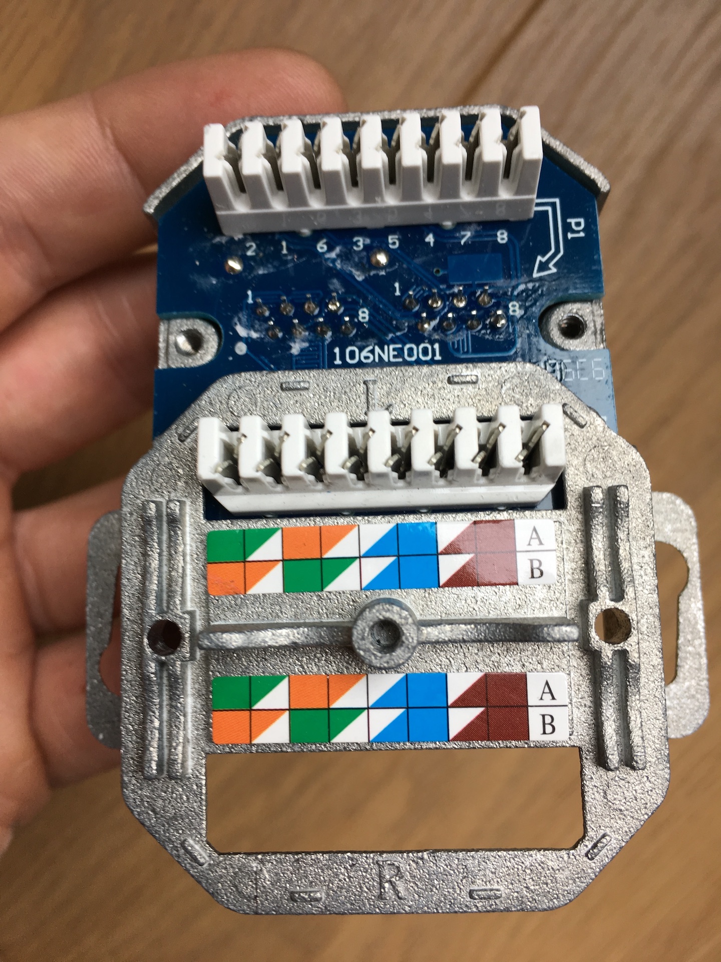
ANSI/TIA-568 is a technical standard for commercial building cabling for telecommunications products and services. The title of the standard is ''Commercial Building Telecommunications Cabling Standard'' and is published by the Telecommunications Industry Association (TIA), a body accredited by the American National Standards Institute (ANSI). , the revision status of the standard is ''ANSI/TIA-568-E'', published 2020, which replaced ANSI/TIA-568-D of 2015, revision C of 2009, revision B of 2001, and revision A of 1995, and the initial issue of 1991, which are now obsolete. Perhaps the best-known features of ANSI/TIA-568 are the pin and pair assignments for eight-conductor 100-ohm balanced twisted pair cabling. These assignments are named ''T568A'' and ''T568B''. History ANSI/TIA-568 was developed through the efforts of more than 60 contributing organizations including manufacturers, end-users, and consultants. Work on the standard began with the Electronic Industries Alliance (EI ... [...More Info...] [...Related Items...] OR: [Wikipedia] [Google] [Baidu] [Amazon] |
USB Type-A Receptacle White
Universal Serial Bus (USB) is an industry standard, developed by USB Implementers Forum (USB-IF), for digital data transmission and power delivery between many types of electronics. It specifies the architecture, in particular the physical interfaces, and communication protocols to and from ''hosts'', such as personal computers, to and from peripheral ''devices'', e.g. displays, keyboards, and mass storage devices, and to and from intermediate ''hubs'', which multiply the number of a host's ports. Introduced in 1996, USB was originally designed to standardize the connection of peripherals to computers, replacing various interfaces such as serial ports, parallel ports, game ports, and Apple Desktop Bus (ADB) ports. Early versions of USB became commonplace on a wide range of devices, such as keyboards, mice, cameras, printers, scanners, flash drives, smartphones, game consoles, and power banks. USB has since evolved into a standard to replace virtually all common ports on ... [...More Info...] [...Related Items...] OR: [Wikipedia] [Google] [Baidu] [Amazon] |
Crossover Cable
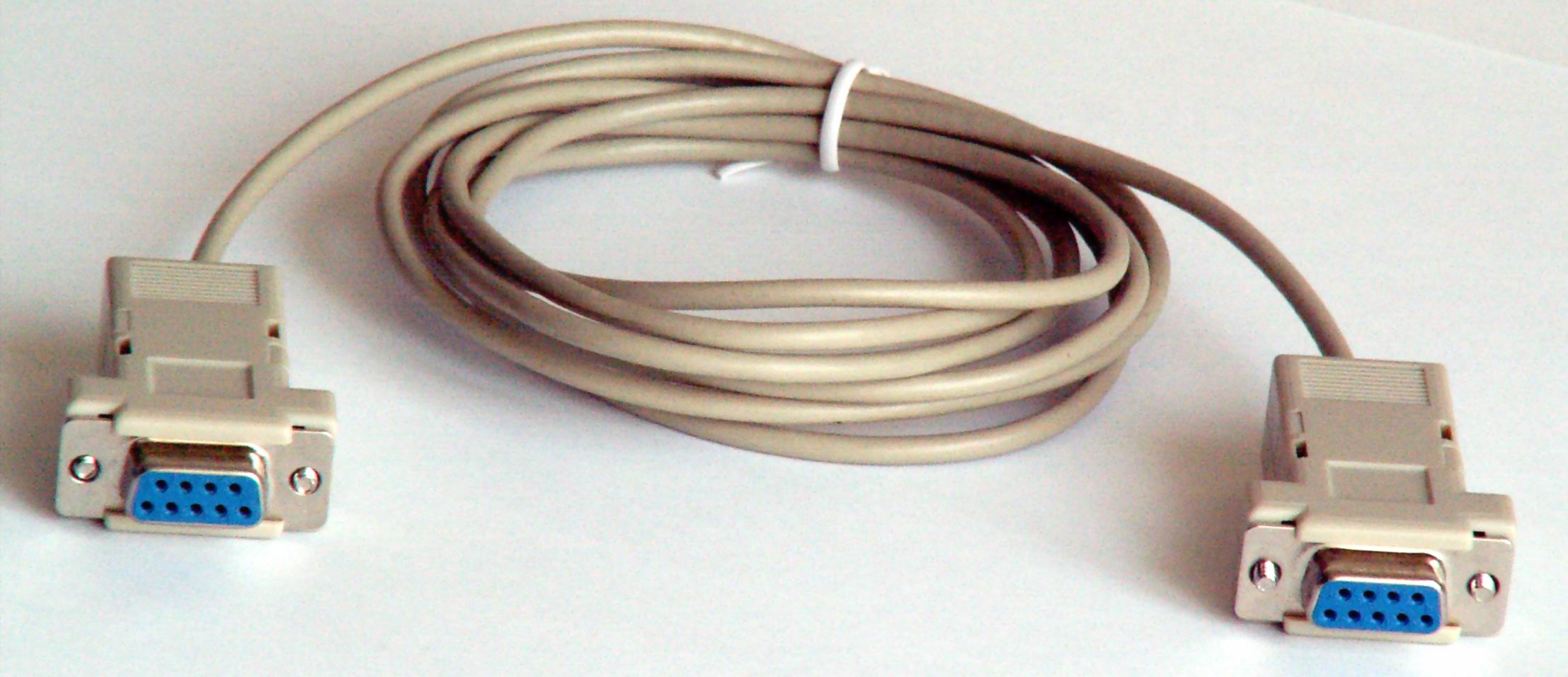
A crossover cable connects two devices of the same type, for example Data terminal equipment, DTE-DTE or Data circuit-terminating equipment, DCE-DCE, usually connected asymmetrically (DTE-DCE), by a modified electrical cable, cable called a crosslink. Such a distinction between devices was introduced by IBM. The crossing of wires in a cable or in a connector adaptor allows: * connecting two devices directly, output of one to input of the other, * letting two terminal (DTE) devices communicate without an interconnecting Ethernet hub, hub knot, i.e. Personal computer, PCs, * linking two or more hubs, Network switch, switches or Router (computing), routers (DCE) together, possibly to work as one wider device. In contrast, a straight-through cable uses direct wiring to connect complementary devices, e.g. a PC to a switch. Concept Straight-through cables are used for most applications, but crossover cables are required in others. In a straight-through cable, pins on one end corres ... [...More Info...] [...Related Items...] OR: [Wikipedia] [Google] [Baidu] [Amazon] |
4000 Series
The 4000 series is a CMOS logic family of integrated circuits (ICs) first introduced in 1968 by RCA. It was slowly migrated into the 4000B buffered series after about 1975. It had a much wider supply voltage range than any contemporary logic family (3V to 18V recommended range for "B" series). Almost all IC manufacturers active during this initial era fabricated models for this series. Its naming convention is still in use today. History The 4000 series was introduced as the ''CD4000 COS/MOS'' series in 1968 by RCA as a lower power and more versatile alternative to the 7400 series of transistor-transistor logic (TTL) chips. The logic functions were implemented with the newly introduced Complementary Metal–Oxide–Semiconductor (CMOS) technology. While initially marketed with "COS/MOS" labeling by RCA (which stood for Complementary Symmetry Metal-Oxide Semiconductor), the shorter ''CMOS'' terminology emerged as the industry preference to refer to the technology. The first chi ... [...More Info...] [...Related Items...] OR: [Wikipedia] [Google] [Baidu] [Amazon] |
Schematic
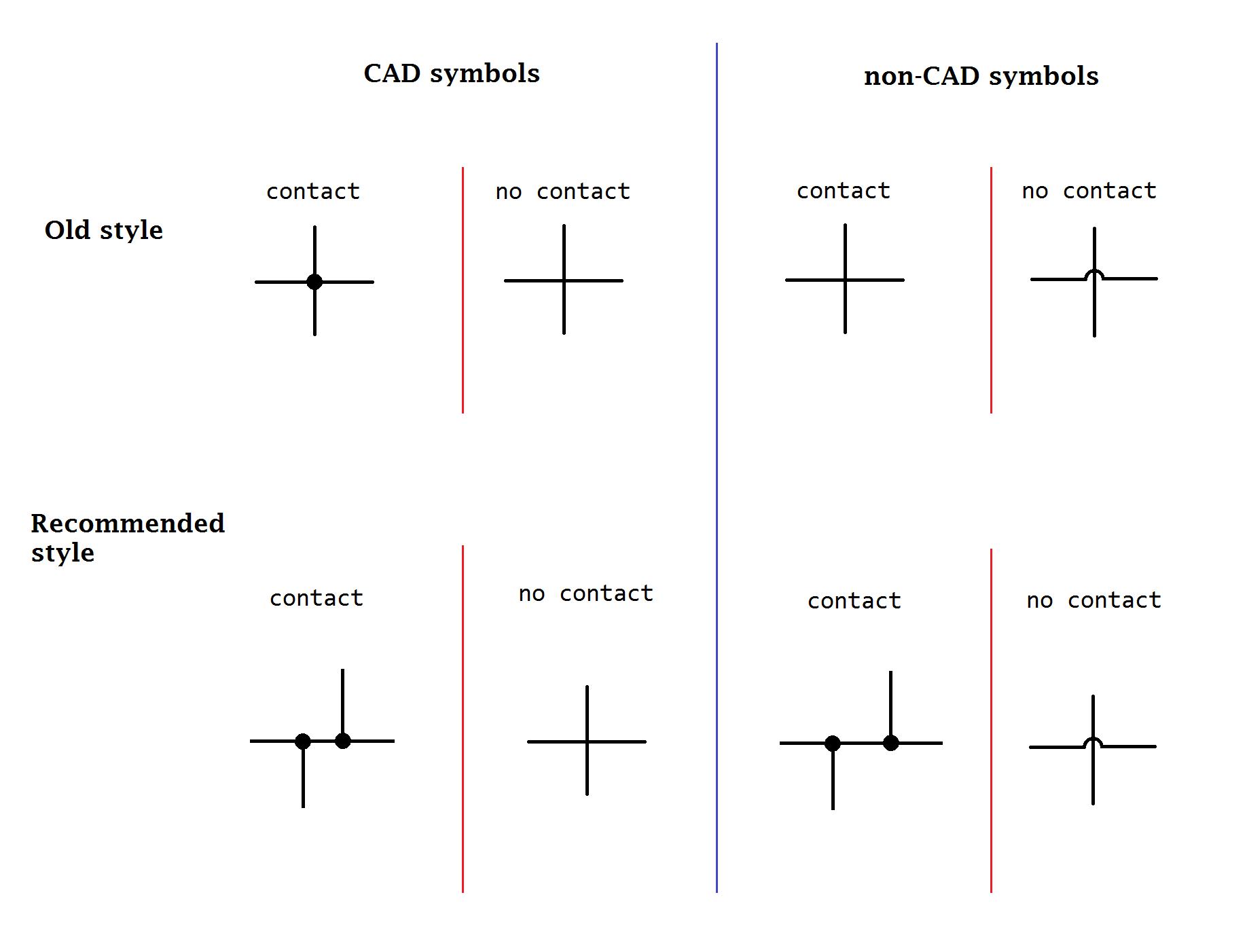
A schematic, or schematic diagram, is a designed representation of the elements of a system using abstract, graphic symbols rather than realistic pictures. A schematic usually omits all details that are not relevant to the key information the schematic is intended to convey, and may include oversimplified elements in order to make this essential meaning easier to grasp, as well as additional organization of the information. For example, a subway map intended for passengers may represent a subway station with a dot. The dot is not intended to resemble the actual station at all but aims to give the viewer information without unnecessary visual clutter. A schematic diagram of a chemical process uses symbols in place of detailed representations of the vessels, piping, valves, pumps, and other equipment that compose the system, thus emphasizing the functions of the individual elements and the interconnections among them and suppresses their physical details. In an electronic circuit d ... [...More Info...] [...Related Items...] OR: [Wikipedia] [Google] [Baidu] [Amazon] |
Circuit Diagram
A circuit diagram (or: wiring diagram, electrical diagram, elementary diagram, electronic schematic) is a graphical representation of an Electrical network, electrical circuit. A pictorial circuit diagram uses simple images of components, while a schematic diagram shows the components and interconnections of the circuit using standardized symbolic representations. The presentation of the interconnections between circuit components in the schematic diagram does not necessarily correspond to the physical arrangements in the finished device. Unlike a block diagram or Integrated circuit layout, layout diagram, a circuit diagram shows the actual electrical connections. A drawing meant to depict the physical arrangement of the wires and the components they connect is called ''artwork'' or ''Integrated circuit layout, layout'', ''physical design'', or ''wiring diagram''. Circuit diagrams are used for the design (circuit design), construction (such as Printed circuit board, PCB layout ... [...More Info...] [...Related Items...] OR: [Wikipedia] [Google] [Baidu] [Amazon] |
Piping And Instrumentation Diagram
A Piping and Instrumentation Diagram (P&ID) is a detailed diagram in the process industry which shows process equipment together with the instrumentation and control devices. It is also called as mechanical flow diagram (MFD). Superordinate to the P&ID is the process flow diagram (PFD) which indicates the more general flow of plant processes and the relationship between major equipment of a plant facility. Contents and function A piping and instrumentation diagram (P&ID) is defined as follows: # A diagram which shows the interconnection of process equipment and the instrumentation used to control the process. In the process industry, a Symbolic language (engineering), standard set of symbols is used to prepare drawings of processes. The instrument symbols used in these drawings are generally based on International Society of Automation (ISA) Standard S5.1 # The primary schematic drawing used for laying out a process control installation. They usually contain the following inf ... [...More Info...] [...Related Items...] OR: [Wikipedia] [Google] [Baidu] [Amazon] |
Datasheet
A datasheet, data sheet, or spec sheet is a document that summarizes the performance and other characteristics of a product, machine, component (e.g., an electronic component), material, subsystem (e.g., a power supply), or software in sufficient detail that allows a buyer to understand what the product is and a design engineer to understand the role of the component in the overall system. Typically, a datasheet is created by the manufacturer and begins with an introductory page describing the rest of the document, followed by listings of specific characteristics, with further information on the wikt:connectivity, connectivity of the devices. In cases where there is relevant source code to include, it is usually attached near the end of the document or separated into another file. Datasheets are created, stored, and distributed via product information management or product data management systems. Depending on the specific purpose, a datasheet may offer an average value, a typic ... [...More Info...] [...Related Items...] OR: [Wikipedia] [Google] [Baidu] [Amazon] |
LM741 Pinout Round
An operational amplifier (often op amp or opamp) is a DC-coupled electronic voltage amplifier with a differential input, a (usually) single-ended output, and an extremely high gain. Its name comes from its original use of performing mathematical operations in analog computers. By using negative feedback, an op amp circuit's characteristics (e.g. its gain, input and output impedance, bandwidth, and functionality) can be determined by external components and have little dependence on temperature coefficients or engineering tolerance in the op amp itself. This flexibility has made the op amp a popular building block in analog circuits. Today, op amps are used widely in consumer, industrial, and scientific electronics. Many standard integrated circuit op amps cost only a few cents; however, some integrated or hybrid operational amplifiers with special performance specifications may cost over . Op amps may be packaged as components or used as elements of more complex integrated ... [...More Info...] [...Related Items...] OR: [Wikipedia] [Google] [Baidu] [Amazon] |
4017 Pinout
4 (four) is a number, numeral and digit. It is the natural number following 3 and preceding 5. It is a square number, the smallest semiprime and composite number, and is considered unlucky in many East Asian cultures. Evolution of the Hindu-Arabic digit Brahmic numerals represented 1, 2, and 3 with as many lines. 4 was simplified by joining its four lines into a cross that looks like the modern plus sign. The Shunga would add a horizontal line on top of the digit, and the Kshatrapa and Pallava evolved the digit to a point where the speed of writing was a secondary concern. The Arabs' 4 still had the early concept of the cross, but for the sake of efficiency, was made in one stroke by connecting the "western" end to the "northern" end; the "eastern" end was finished off with a curve. The Europeans dropped the finishing curve and gradually made the digit less cursive, ending up with a digit very close to the original Brahmin cross. While the shape of the character for ... [...More Info...] [...Related Items...] OR: [Wikipedia] [Google] [Baidu] [Amazon] |
Clock Signal
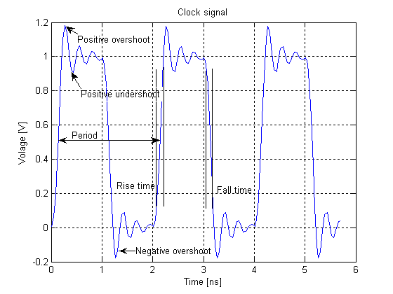
In electronics and especially synchronous digital circuits, a clock signal (historically also known as ''logic beat'') is an electronic logic signal (voltage or current) which oscillates between a high and a low state at a constant frequency and is used like a metronome to synchronize actions of digital circuits. In a synchronous logic circuit, the most common type of digital circuit, the clock signal is applied to all storage devices, flip-flops and latches, and causes them all to change state simultaneously, preventing race conditions. A clock signal is produced by an electronic oscillator called a clock generator. The most common clock signal is in the form of a square wave with a 50% duty cycle. Circuits using the clock signal for synchronization may become active at either the rising edge, falling edge, or, in the case of double data rate, both in the rising and in the falling edges of the clock cycle. Digital circuits Most integrated circuits (ICs) of suffi ... [...More Info...] [...Related Items...] OR: [Wikipedia] [Google] [Baidu] [Amazon] |


