|
Watts Linkage
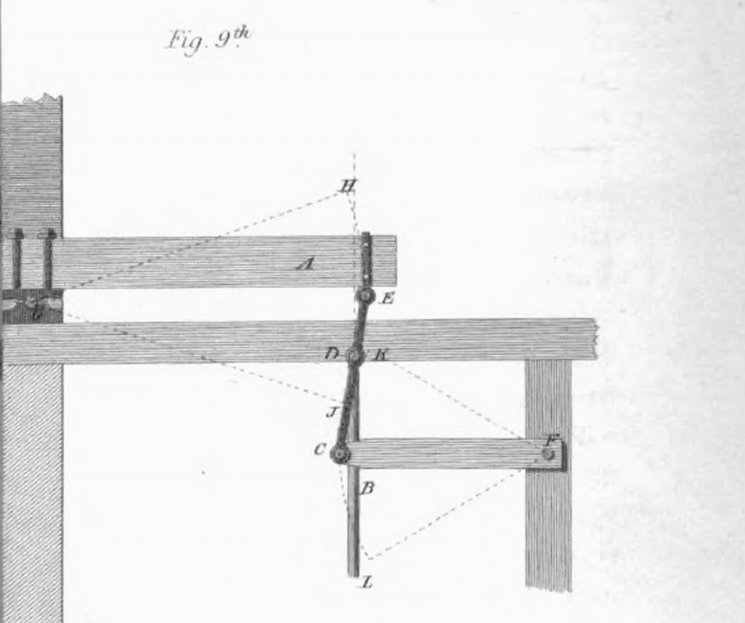
In kinematics, Watt's linkage (also known as the parallel linkage) is a type of mechanical linkage invented by James Watt in which the central moving point of the linkage is constrained to travel on a nearly straight line. It was described in Watt's patent specification of 1784 for the Watt steam engine. Today it is used in automobile suspensions, allowing the axle of a vehicle to travel vertically while preventing sideways motion. Description Watt's linkage consists of three bars bolted together in a chain. The chain of bars consists of two end bars and a middle bar. The middle bar is bolted at each of its ends to one of the ends of each outer bar. The two outer bars are of equal length, and are longer than the middle bar. The three bars can pivot around the two bolts. The outer endpoints of the long bars are fixed in place relative to each other, but otherwise the three bars are free to pivot around the two joints where they meet. In linkage analysis there is an imaginary ... [...More Info...] [...Related Items...] OR: [Wikipedia] [Google] [Baidu] |
Watt's Curve
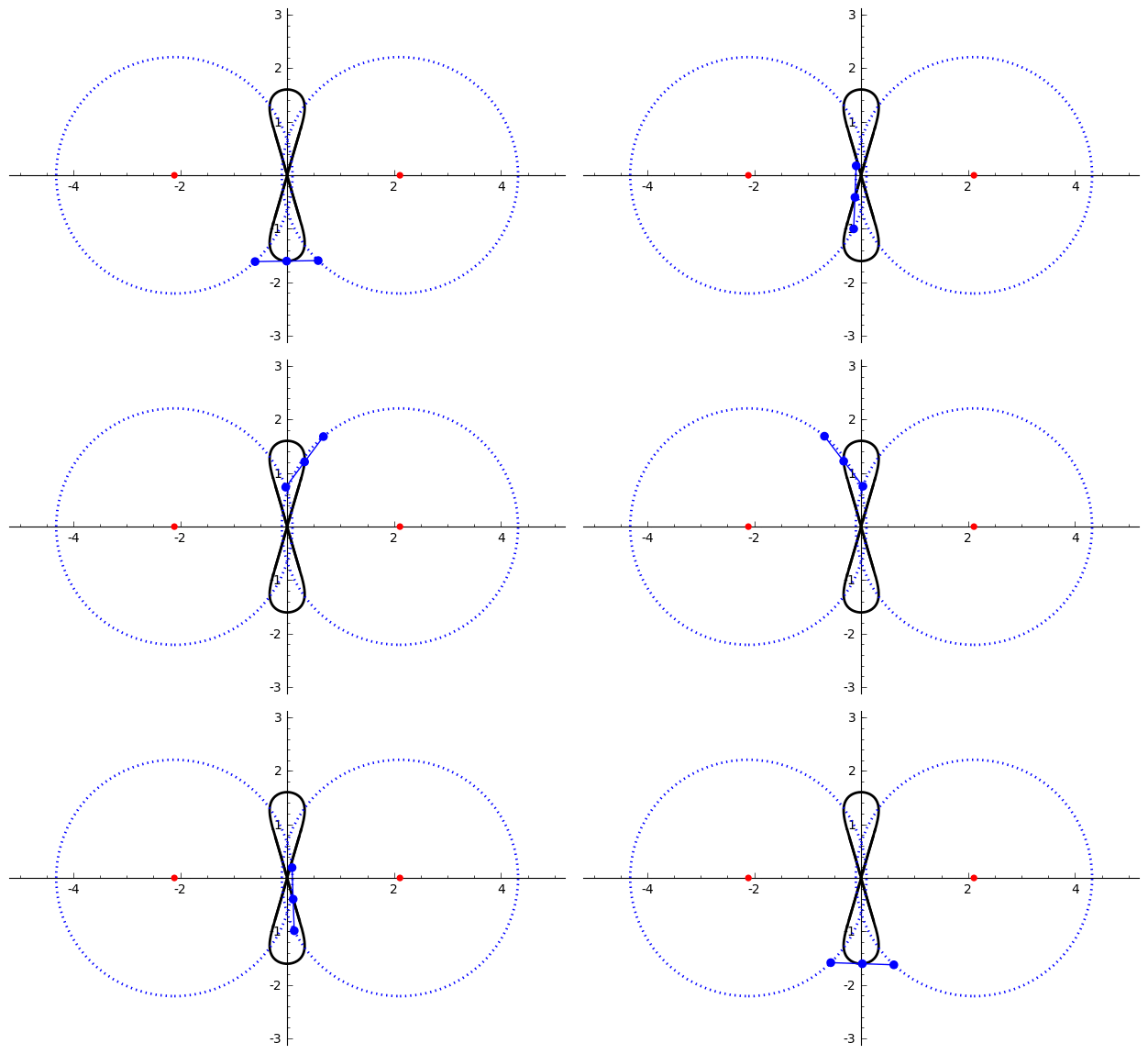
In mathematics, Watt's curve is a tricircular plane algebraic curve of degree six. It is generated by two circles of radius ''b'' with centers distance 2''a'' apart (taken to be at (±''a'', 0)). A line segment of length 2''c'' attaches to a point on each of the circles, and the midpoint of the line segment traces out the Watt curve as the circles rotate partially back and forth or completely around. It arose in connection with James Watt's pioneering work on the steam engine. The equation of the curve can be given in polar coordinates as :r^2=b^2-\left \sin\theta\pm\sqrt\right2. Derivation Polar coordinates The polar equation for the curve can be derived as follows: Working in the complex plane, let the centers of the circles be at ''a'' and ''−a'', and the connecting segment have endpoints at ''−a''+''be''''i'' λ and ''a''+''be''''i'' ρ. Let the angle of inclination of the segment be ψ with its midpoint at ''re''''i'' θ. Then the endpoints are also given by ' ... [...More Info...] [...Related Items...] OR: [Wikipedia] [Google] [Baidu] |
Beam Axle
A beam axle, rigid axle or solid axle is a dependent suspension design in which a set of wheels is connected laterally by a single beam or shaft. Beam axles were once commonly used at the rear wheels of a vehicle, but historically they have also been used as front axles in four-wheel-drive vehicles. In most automobiles, beam axles have been replaced with front and rear independent suspensions. Implementation With a beam axle the camber angle between the wheels is the same no matter where it is in the travel of the suspension. A beam axle's fore & aft location is constrained by either: trailing arms, semi-trailing arms, radius rods, or leaf springs. The lateral location can be constrained by a Panhard rod, a Scott Russell linkage or a Watt's linkage, or some other arrangement, most commonly by the leaf springs. Shock absorbers and either leaf springs, coil springs, or air bags are used to control vertical movement. The Twist-beam rear suspension is a similar suspension desi ... [...More Info...] [...Related Items...] OR: [Wikipedia] [Google] [Baidu] |
Alstom Link Diameter 762mm FS075
Alstom SA is a French multinational rolling stock manufacturer operating worldwide in rail transport markets, active in the fields of passenger transportation, signalling, and locomotives, with products including the AGV, TGV, Eurostar, Avelia and New Pendolino high-speed trains, in addition to suburban, regional and metro trains, and Citadis trams. Alsthom (originally Als-Thom) was formed by a merger between Compagnie Française Thomson-Houston and the electric engineering division of Société Alsacienne de Constructions Mécaniques in 1928. Significant later acquisitions included the Constructions Electriques de France (1932), shipbuilder Chantiers de l'Atlantique (1976), and parts of ACEC (Belgium, late-1980s). A merger with parts of the General Electric Company (UK) formed GEC Alsthom in 1989. Throughout the 1990s, the company expanded its holdings in the rail sector, via the acquisition of German rolling stock manufacturer Linke-Hofmann-Busch and Italian rail signal ... [...More Info...] [...Related Items...] OR: [Wikipedia] [Google] [Baidu] |
Crossness Pumping Station
The Crossness Pumping Station is a former sewage pumping station designed by the Metropolitan Board of Works's chief engineer Sir Joseph Bazalgette and architect Charles Henry Driver. It is located at Crossness Sewage Treatment Works, at the eastern end of the Southern Outfall Sewer and the Ridgeway path in the London Borough of Bexley. Constructed between 1859 and 1865 by William Webster, as part of Bazalgette's redevelopment of the London sewerage system, it features spectacular ornamental cast ironwork, that Nikolaus Pevsner described as "a masterpiece of engineering – a Victorian cathedral of ironwork". It is adjacent to Erith Marshes, a grazing marsh, the northern part of which is designated as Crossness Nature Reserve. This provides a valuable habitat for creatures ranging from moths to small amphibians and water voles. Opening The Southern Outfall Works, as the complex was originally called, was officially opened on 4 April 1865, by Edward, Prince of Wales, at ... [...More Info...] [...Related Items...] OR: [Wikipedia] [Google] [Baidu] |
Double-acting Cylinder
In mechanical engineering, the cylinders of reciprocating engines are often classified by whether they are single- or double-acting, depending on how the working fluid acts on the piston. Single-acting A single-acting cylinder in a reciprocating engine is a cylinder in which the working fluid acts on one side of the piston only. A single-acting cylinder relies on the load, springs, other cylinders, or the momentum of a flywheel, to push the piston back in the other direction. Single-acting cylinders are found in most kinds of reciprocating engine. They are almost universal in internal combustion engines (e.g. petrol and diesel engines) and are also used in many external combustion engines such as Stirling engines and some steam engines. They are also found in pumps and hydraulic rams. Double-acting A double-acting cylinder is a cylinder in which the working fluid acts alternately on both sides of the piston. In order to connect the piston in a double-acting cylinder t ... [...More Info...] [...Related Items...] OR: [Wikipedia] [Google] [Baidu] |
Chebyshev Linkage
In kinematics, Chebyshev's linkage is a four-bar linkage that converts rotational motion to approximate linear motion. It was invented by the 19th-century mathematician Pafnuty Chebyshev, who studied theoretical problems in kinematic mechanisms. One of the problems was the construction of a linkage that converts a rotary motion into an approximate straight-line motion (a straight line mechanism). This was also studied by James Watt in his improvements to the steam engine, which resulted in Watt's linkage. – Cross link straight-line mechanism Equations of motion The motion of the linkage can be constrained to an input angle that may be changed through velocities, forces, etc. The input angles can be either link ''L''2 with the horizontal or link ''L''4 with the ...[...More Info...] [...Related Items...] OR: [Wikipedia] [Google] [Baidu] |
Straight Line Mechanism
A straight-line mechanism is a mechanism that converts any type of rotary or angular motion to perfect or near-perfect straight-line motion, or ''vice-versa''. Straight-line motion is linear motion of definite length or "stroke", every forward stroke being followed by a return stroke, giving reciprocating motion. The first such mechanism, patented in 1784 by James Watt, produced approximate straight-line motion, referred to by Watt as parallel motion. Straight-line mechanisms are used in a variety of applications, such as engines, vehicle suspensions, walking robots, and rover wheels. History In the late eighteenth century, before the development of the planer and the milling machine, it was extremely difficult to machine straight, flat surfaces. During that era, much thought was given to the problem of attaining a straight-line motion, as this would allow the flat surfaces to be machined. To find a solution to the problem, the first straight line mechanism was dev ... [...More Info...] [...Related Items...] OR: [Wikipedia] [Google] [Baidu] |
Hart's Inversor
Hart's inversors are two planar mechanisms that provide a perfect straight line motion using only rotary joints. They were invented and published by Harry Hart in 1874–5. Hart's first inversor, also known as ''Hart's W-frame'', is based on an antiparallelogram. The addition of fixed points and a driving arm make it a 6-bar linkage. It can be used to convert rotary motion to a perfect straight line by fixing a point on one short link and driving a point on another link in a circular arc. Hart's second inversor, also known as ''Hart's A-frame'', is less flexible in its dimensions, but has the useful property that the motion perpendicularly bisects the fixed base points. It is shaped like a capital A – a stacked trapezium and triangle. It is also a 6-bar linkage. Example dimensions These are the example dimensions that you see in the animations on the right. Mecanismo de Hart (2).png, Mecanismo de Hart.png, See also ... [...More Info...] [...Related Items...] OR: [Wikipedia] [Google] [Baidu] |
Peaucellier–Lipkin Linkage
The Peaucellier–Lipkin linkage (or Peaucellier–Lipkin cell, or Peaucellier–Lipkin inversor), invented in 1864, was the first true planar straight line mechanism – the first planar linkage capable of transforming rotary motion into perfect straight-line motion, and vice versa. It is named after Charles-Nicolas Peaucellier (1832–1913), a French army officer, and Yom Tov Lipman Lipkin (1846–1876), a Lithuanian Jew and son of the famed Rabbi Israel Salanter. Until this invention, no planar method existed of converting exact straight-line motion to circular motion, without reference guideways. In 1864, all power came from steam engines, which had a piston moving in a straight-line up and down a cylinder. This piston needed to keep a good seal with the cylinder in order to retain the driving medium, and not lose energy efficiency due to leaks. The piston does this by remaining perpendicular to the axis of the cylinder, retaining its straight-line moti ... [...More Info...] [...Related Items...] OR: [Wikipedia] [Google] [Baidu] |


