|
Wind Triangle
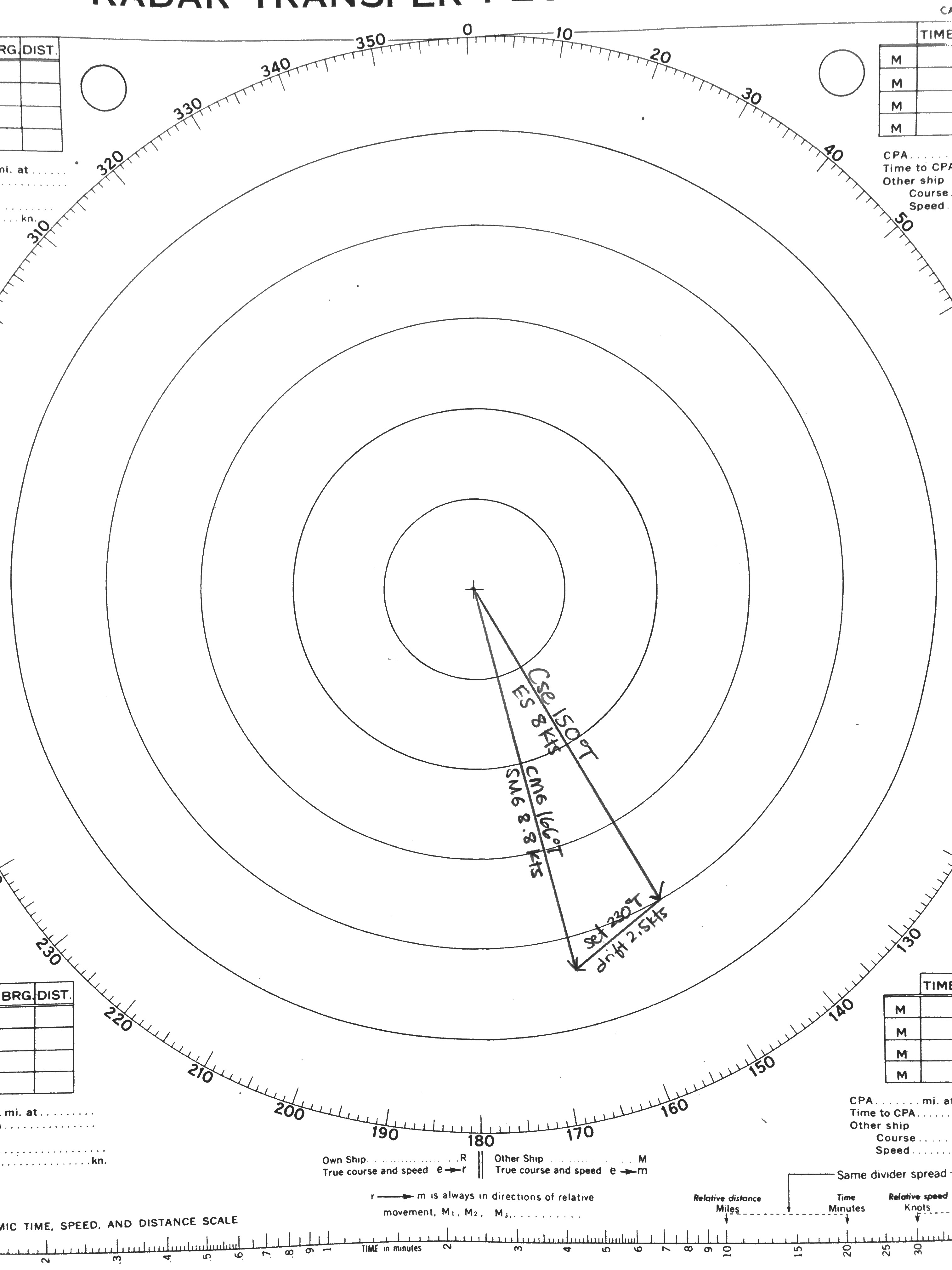
In air navigation, the wind triangle is a graphical representation of the relationship between aircraft motion and wind. It is used extensively in dead reckoning navigation. The wind triangle is a vector diagram, with three vectors. *The air vector represents the motion of the aircraft through the airmass. It is described by true airspeed and true heading. *The wind vector represents the motion of the airmass over the ground. It is described by wind speed and the inverse of wind direction. Note that by convention wind direction is given as the direction the wind is ''from''. In a vector diagram such as the wind triangle, wind direction must be stated as the direction the wind is blowing ''to'', or 180 degrees different from the convention. *The ground vector represents the motion of the aircraft over the ground. It is described by ground track and ground speed. The ground vector is the resultant of algebraically adding the air vector and the wind vector. The wind tri ... [...More Info...] [...Related Items...] OR: [Wikipedia] [Google] [Baidu] |
Estimated Time Of Arrival
The estimated time of arrival (ETA) is the time when a ship, vehicle, aircraft, cargo, person, or emergency service is expected to arrive at a certain place. Overview One of the more common uses of the phrase is in public transportation where the movements of trains, buses, airplanes and the like can be used to generate estimated times of arrival depending on either a static timetable or through measurements on traffic intensity. In this respect, the phrase or its abbreviation is often paired with its complement, estimated time of departure (ETD), to indicate the expected start time of a particular journey. This information is often conveyed to a passenger information system as part of the core functionality of intelligent transportation systems. For example, a certain flight may have a calculated ETA based on the speed by which it has covered the distance traveled so far. The remaining distance is divided by the speed previously measured to roughly estimate the arrival time. This ... [...More Info...] [...Related Items...] OR: [Wikipedia] [Google] [Baidu] |
Set And Drift
The term “set and drift” is used to describe external forces that affect a boat and keep it from following an intended course. To understand and calculate set and drift, one needs to first understand currents. Ocean currents are the horizontal movements of water from one location to another. The movement of water is impacted by: meteorological effects, wind, temperature differences, gravity, and on occasion earthquakes. Set is the current's direction, expressed in true degrees. Drift is the current's speed, which is usually measured in knots. “Leeway” refers to the amount of sidewards translation of a vessel drifting off of or away from the intended course of travel (with no correction or compensation by altering the heading of the vessel such as pointing her into the wind.) Ignoring set and drift can cause a mariner to get off their desired course, sometimes by hundreds of miles. A mariner needs to be able to steer the ship and compensate for the effects of set and drift ... [...More Info...] [...Related Items...] OR: [Wikipedia] [Google] [Baidu] |
Automatic Direction Finder
An automatic direction finder (ADF) is a marine or aircraft Radio navigation, radio-navigation instrument that automatically and continuously displays the relative bearing from the ship or aircraft to a suitable radio station. ADF receivers are normally tuned to aviation or marine NDBs (Non-Directional Beacon) operating in the LW band between 190 – 535 kHz. Like RDF (Radio direction finder, Radio Direction Finder) units, most ADF receivers can also receive medium wave (AM) broadcast stations, though these are less reliable for navigational purposes. The operator tunes the ADF receiver to the correct frequency and verifies the identity of the beacon by listening to the Morse code signal transmitted by the NDB. On marine ADF receivers, the motorized ferrite-bar antenna atop the unit (or remotely mounted on the masthead) would rotate and lock when reaching the null of the desired station. A centerline on the antenna unit moving atop a compass rose indicated in degrees the bea ... [...More Info...] [...Related Items...] OR: [Wikipedia] [Google] [Baidu] |
Distance Measuring Equipment
In aviation, distance measuring equipment (DME) is a radio navigation technology that measures the slant range (distance) between an aircraft and a ground station by timing the propagation delay of radio signals in the frequency band between 960 and 1215 megahertz (MHz). Line-of-visibility between the aircraft and ground station is required. An interrogator (airborne) initiates an exchange by transmitting a pulse pair, on an assigned 'channel', to the transponder ground station. The channel assignment specifies the carrier frequency and the spacing between the pulses. After a known delay, the transponder replies by transmitting a pulse pair on a frequency that is offset from the interrogation frequency by 63 MHz and having specified separation.''Annex 10 to the Convention on International Civil Aviation, Volume I – Radio Navigation Aids''; International Civil Aviation Organization; International Standards and Recommended Practices. DME systems are used worldwide, usi ... [...More Info...] [...Related Items...] OR: [Wikipedia] [Google] [Baidu] |
VHF Omnidirectional Range
Very High Frequency Omnidirectional Range Station (VOR) is a type of short-range VHF radio navigation system for aircraft, enabling aircraft with a VOR receiver to determine the azimuth (also radial), referenced to magnetic north, between the aircraft to/from fixed VOR ground transmitter, radio beacons. VOR and the first DME(1950) system (referenced to 1950 since different from today's DME/N) to provide the slant range distance, were developed in the United States as part of a U.S. civil/military program for Aeronautical Navigation Aids in 1945. Deployment of VOR and DME(1950) began in 1949 by the U.S. CAA (Civil Aeronautics Administration). ICAO standardized VOR and DME(1950) in 1950 in ICAO Annex ed.1. Frequencies for the use of VOR are standardized in the very high frequency (VHF) band between 108.00 and 117.95 MHz Chapter 3, Table A. To improve azimuth accuracy of VOR even under difficult siting conditions, Doppler VOR (DVOR) was developed in the 1960s. VOR is accordi ... [...More Info...] [...Related Items...] OR: [Wikipedia] [Google] [Baidu] |
Global Positioning System
The Global Positioning System (GPS) is a satellite-based hyperbolic navigation system owned by the United States Space Force and operated by Mission Delta 31. It is one of the global navigation satellite systems (GNSS) that provide geolocation and time information to a GPS receiver anywhere on or near the Earth where there is an unobstructed line of sight to four or more GPS satellites. It does not require the user to transmit any data, and operates independently of any telephone or Internet reception, though these technologies can enhance the usefulness of the GPS positioning information. It provides critical positioning capabilities to military, civil, and commercial users around the world. Although the United States government created, controls, and maintains the GPS system, it is freely accessible to anyone with a GPS receiver. Overview The GPS project was started by the U.S. Department of Defense in 1973. The first prototype spacecraft was launched in 1978 an ... [...More Info...] [...Related Items...] OR: [Wikipedia] [Google] [Baidu] |
Inertial Navigation System
An inertial navigation system (INS; also inertial guidance system, inertial instrument) is a navigation device that uses motion sensors (accelerometers), rotation sensors (gyroscopes) and a computer to continuously calculate by dead reckoning the position, the orientation, and the velocity (direction and speed of movement) of a moving object without the need for external references. Often the inertial sensors are supplemented by a barometric altimeter and sometimes by magnetic sensors (magnetometers) and/or speed measuring devices. INSs are used on mobile robots and on vehicles such as ships, aircraft, submarines, guided missiles, and spacecraft. Older INS systems generally used an inertial platform as their mounting point to the vehicle and the terms are sometimes considered synonymous. Design Inertial navigation is a self-contained navigation technique in which measurements provided by accelerometers and gyroscopes are used to track the position and orientation of an object ... [...More Info...] [...Related Items...] OR: [Wikipedia] [Google] [Baidu] |
Air Data Computer
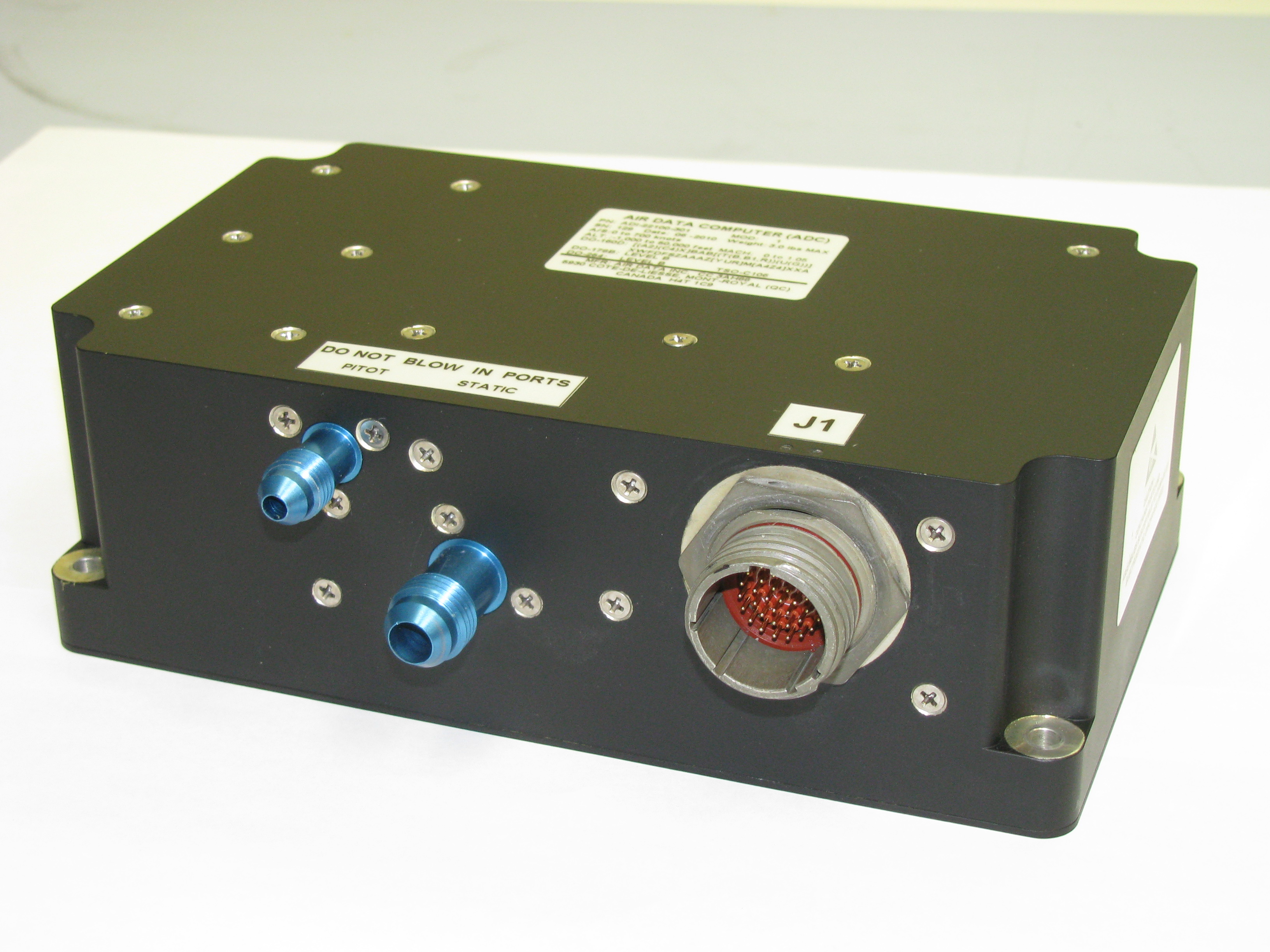
An air data computer (ADC) or central air data computer (CADC) computes altitude, vertical speed, air speed, and Mach number from pressure and temperature inputs. It is an essential avionics component found in modern aircraft. This computer, rather than individual flight instruments, instruments, can determine the calibrated airspeed, Mach number, altitude, and vertical speed indicator, altitude trend data from an aircraft's pitot-static system. In some very high-speed aircraft such as the Space Shuttle, equivalent airspeed is calculated instead of calibrated airspeed. Air data computers usually also have an input of total air temperature. This enables the computation of static air temperature and true airspeed. Models In Airbus aircraft the air data computer is combined with attitude, heading and navigation sources in a single unit known as the Air Data Inertial Reference Unit (ADIRU) which has now been replaced by the Global Navigation Air Data Inertial Reference System (GNADI ... [...More Info...] [...Related Items...] OR: [Wikipedia] [Google] [Baidu] |
Flight Management System
A flight management system (FMS) is a fundamental component of a modern airliner's avionics. An FMS is a specialized computer system that automates a wide variety of in-flight tasks, reducing the workload on the flight crew to the point that modern civilian aircraft no longer carry flight engineers or navigators. A primary function is in-flight management of the flight plan. Using various sensors (such as GPS and INS often backed up by radio navigation) to determine the aircraft's position, the FMS can guide the aircraft along the flight plan. From the cockpit, the FMS is normally controlled through a Control Display Unit (CDU) which incorporates a small screen and keyboard or touchscreen. The FMS sends the flight plan for display to the Electronic Flight Instrument System (EFIS), Navigation Display (ND), or Multifunction Display (MFD). The FMS can be summarised as being a dual system consisting of the Flight Management Computer (FMC), CDU and a cross talk bus. The modern F ... [...More Info...] [...Related Items...] OR: [Wikipedia] [Google] [Baidu] |
Protractor
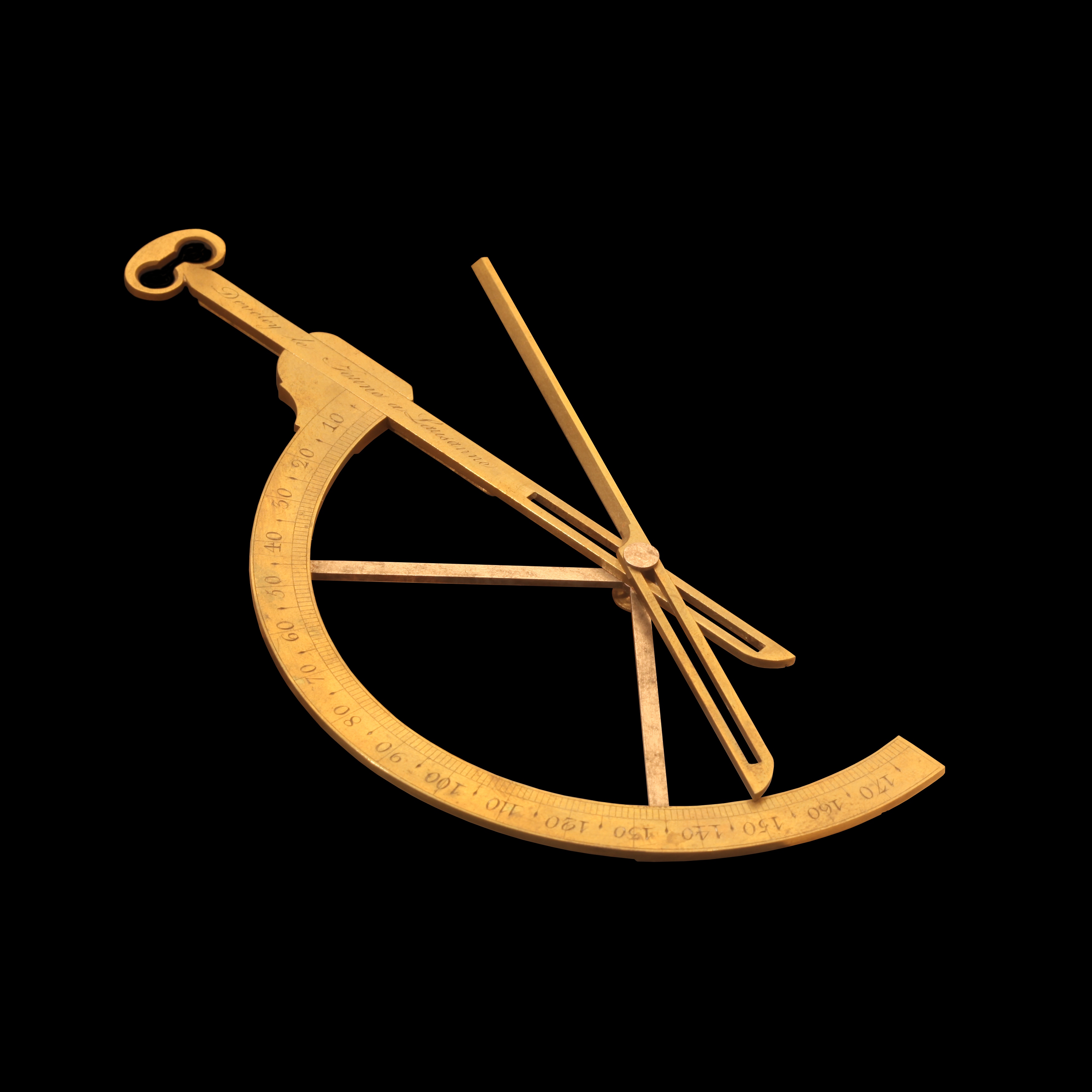
A goniometer is an instrument that either measures an angle or allows an object to be rotated to a precise angular position. The term goniometry derives from two Greek words, γωνία (''gōnía'') 'angle' and μέτρον (''métron'') ' measure'. The protractor is a commonly used type in the fields of mechanics, engineering, and geometry. The first known description of a goniometer, based on the astrolabe, was by Gemma Frisius in 1538. Protractor A protractor is a measuring instrument, typically made of transparent plastic, for measuring angles. Some protractors are simple half-discs or full circles. More advanced protractors, such as the bevel protractor, have one or two swinging arms, which can be used to help measure the angle. Most protractors measure angles in degrees (°). Radian-scale protractors measure angles in radians. Most protractors are divided into 180 equal parts. Some precision protractors further divide degrees into arcminutes. A protractor divided ... [...More Info...] [...Related Items...] OR: [Wikipedia] [Google] [Baidu] |
Aeronautical Chart
An aeronautical chart is a map designed to assist in the navigation of aircraft, much as nautical charts do for watercraft, or a roadmap does for drivers. Using these charts and other tools, pilots are able to determine their position, safe altitude, best route to a destination, navigation aids along the way, alternative landing areas in case of an in-flight emergency, and other useful information such as radio frequencies and airspace boundaries. There are charts for all land masses on Earth, and long-distance charts for trans-oceanic travel. Specific charts are used for each phase of a flight and may vary from a map of a particular airport facility to an overview of the instrument routes covering an entire continent (e.g., global navigation charts), and many types in between. Visual flight charts are categorized according to their scale, which is proportional to the size of the area covered by one map. The amount of detail is necessarily reduced when larger areas are repr ... [...More Info...] [...Related Items...] OR: [Wikipedia] [Google] [Baidu] |


