|
JFET
The junction field-effect transistor (JFET) is one of the simplest types of field-effect transistor. JFETs are three-terminal semiconductor devices that can be used as electronically controlled switches or resistors, or to build amplifiers. Unlike bipolar junction transistors, JFETs are exclusively voltage-controlled in that they do not need a biasing current. Electric charge flows through a semiconducting channel between ''source'' and ''drain'' terminals. By applying a reverse bias voltage to a ''gate'' terminal, the channel is '' pinched'', so that the electric current is impeded or switched off completely. A JFET is usually conducting when there is zero voltage between its gate and source terminals. If a potential difference of the proper polarity is applied between its gate and source terminals, the JFET will be more resistive to current flow, which means less current would flow in the channel between the source and drain terminals. JFETs are sometimes referred to a ... [...More Info...] [...Related Items...] OR: [Wikipedia] [Google] [Baidu] |
Voltage-controlled Resistor
A voltage-controlled resistor (VCR) is a three-terminal active device with one input port and two output ports. The input-port voltage controls the value of the resistor between the output ports. VCRs are most often built with field-effect transistors (FETs). Two types of FETs are often used: the JFET and the MOSFET. There are both Floating ground, floating voltage-controlled resistors and grounded voltage-controlled resistors. Floating VCRs can be placed between two passive or active components. Grounded VCRs, the more common and less complicated design, require that one port of the voltage-controlled resistor be grounded. Usages Voltage-controlled resistors are one of the most commonly used analog design blocks: adaptive analog filters, automatic gain-control circuits, clock generators, compressors, electrometers, energy harvesters, expanders, hearing aids, light dimmers, modulators (mixers), artificial neural networks, programmable-gain amplifiers, phased arrays, phase-locked l ... [...More Info...] [...Related Items...] OR: [Wikipedia] [Google] [Baidu] |
Field-effect Transistor
The field-effect transistor (FET) is a type of transistor that uses an electric field to control the current through a semiconductor. It comes in two types: junction FET (JFET) and metal-oxide-semiconductor FET (MOSFET). FETs have three terminals: ''source'', ''gate'', and ''drain''. FETs control the current by the application of a voltage to the gate, which in turn alters the conductivity between the drain and source. FETs are also known as unipolar transistors since they involve single-carrier-type operation. That is, FETs use either electrons (n-channel) or holes (p-channel) as charge carriers in their operation, but not both. Many different types of field effect transistors exist. Field effect transistors generally display very high input impedance at low frequencies. The most widely used field-effect transistor is the MOSFET (metal–oxide–semiconductor field-effect transistor). History The concept of a field-effect transistor (FET) was first patented by the Austr ... [...More Info...] [...Related Items...] OR: [Wikipedia] [Google] [Baidu] |
IEEE 315-1975 (1993) 8
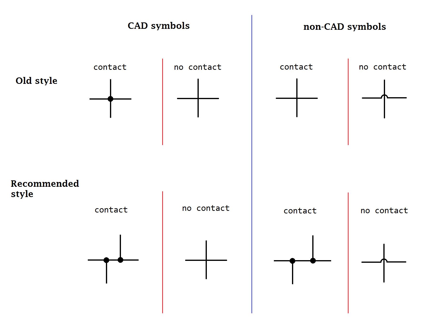
An electronic symbol is a pictogram used to represent various electrical and electronic devices or functions, such as wires, batteries, resistors, and transistors, in a schematic diagram of an electrical or electronic circuit. These symbols are largely standardized internationally today, but may vary from country to country, or engineering discipline, based on traditional conventions. Standards for symbols The graphic symbols used for electrical components in circuit diagrams are covered by national and international standards, in particular: * IEC 60617 (also known as BS 3939). * There is also IEC 61131-3 – for ladder-logic symbols. * JIC JIC (Joint Industrial Council) symbols as approved and adopted by the NMTBA (National Machine Tool Builders Association). They have been extracted from the Appendix of the NMTBA Specification EGPl-1967. * ANSI Y32.2-1975 (also known aIEEE Std 315-1975or CSA Z99-1975). * IEEE Std 91/91a: graphic symbols for logic functions (used in digital ... [...More Info...] [...Related Items...] OR: [Wikipedia] [Google] [Baidu] |
Common Source
In electronics, a common-source amplifier is one of three basic single-stage field-effect transistor (FET) amplifier topologies, typically used as a voltage or transconductance amplifier. The easiest way to tell if a FET is common source, common drain, or common gate is to examine where the signal enters and leaves. The remaining terminal is what is known as "common". In this example, the signal enters the gate, and exits the drain. The only terminal remaining is the source. This is a common-source FET circuit. The analogous bipolar junction transistor circuit may be viewed as a transconductance amplifier or as a voltage amplifier. (See classification of amplifiers). As a transconductance amplifier, the input voltage is seen as modulating the current going to the load. As a voltage amplifier, input voltage modulates the current flowing through the FET, changing the voltage across the output resistance according to Ohm's law. However, the FET device's output resistance typica ... [...More Info...] [...Related Items...] OR: [Wikipedia] [Google] [Baidu] |
Electrical Polarity
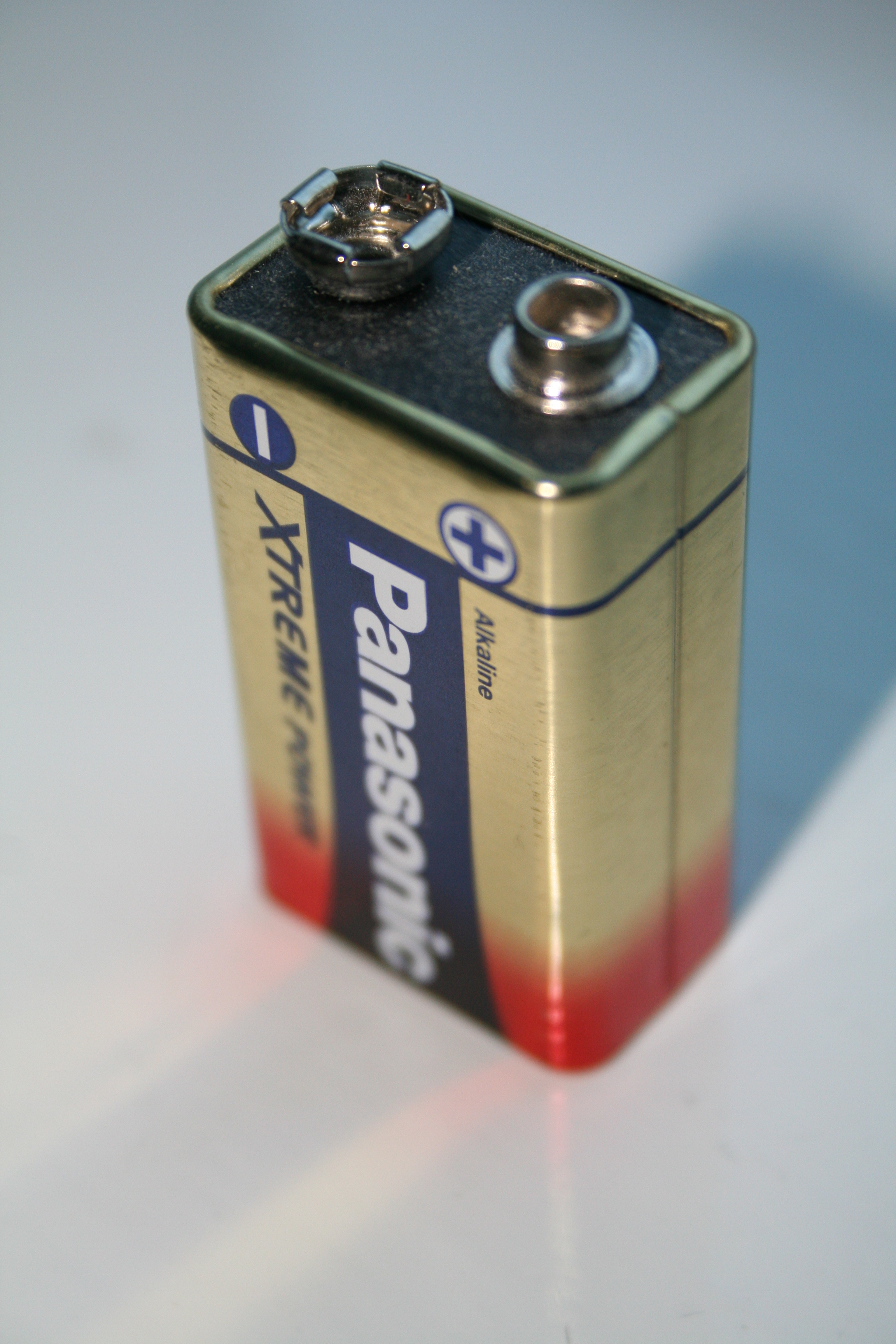
The following Outline (list), outline is provided as an overview of and topical guide to electrical polarity (also called electric polarity). Positive and negative polarity * In electrical engineering, electrical polarity defines the direction in which the electrical current would flow once a source is connected; usually used for the direct current sources, where terminals are traditionally labeled with polarity symbols + (positive) and - (negative), with the conventional current chosen to flow from the positive to negative terminal. ** By analogy, when in electronics a signal is observed across two terminals, the measurement of voltage between the terminals yields opposing signs for the positive and negative polarity. * In physics and chemistry, electric polarity defines the electric charge separation into positive and negative charges within a system or molecule (for example, water molecules have unequal distribution of electrons between the oxygen and hydrogen atoms). The q ... [...More Info...] [...Related Items...] OR: [Wikipedia] [Google] [Baidu] |
Common Drain
In electronics, a common-drain amplifier, also known as a source follower, is one of three basic single-stage field-effect transistor (FET) amplifier topologies, typically used as a voltage buffer. In this circuit (NMOS) the gate terminal of the transistor serves as the signal input, the source is the output, and the drain is ''common'' to both (input and output), hence its name. Because of its low dependence on the load resistor on the voltage gain, it can be used to drive low resistance loads, such as a speaker. The analogous bipolar junction transistor circuit is the common-collector amplifier. This circuit is also commonly called a "stabilizer". In addition, this circuit is used to transform impedances. For example, the Thévenin resistance of a combination of a voltage follower driven by a voltage source with high Thévenin resistance is reduced to only the output resistance of the voltage follower (a small resistance). That resistance reduction makes the combination a mor ... [...More Info...] [...Related Items...] OR: [Wikipedia] [Google] [Baidu] |
Channel Length Modulation
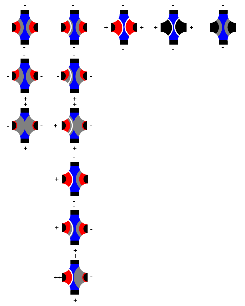
Channel length modulation (CLM) is an effect in field effect transistors, a shortening of the length of the inverted channel region with increase in drain bias for large drain biases. The result of CLM is an increase in current with drain bias and a reduction of output resistance. It is one of several short-channel effects in MOSFET scaling. It also causes distortion in JFET amplifiers. To understand the effect, first the notion of pinch-off of the channel is introduced. The channel is formed by attraction of carriers to the gate, and the current drawn through the channel is nearly a constant independent of drain voltage in saturation mode. However, near the drain, the gate ''and drain'' jointly determine the electric field pattern. Instead of flowing in a channel, beyond the pinch-off point the carriers flow in a subsurface pattern made possible because the drain and the gate both control the current. In the figure at the right, the channel is indicated by a dashed line and ... [...More Info...] [...Related Items...] OR: [Wikipedia] [Google] [Baidu] |
Depletion-mode
In field-effect transistors (FETs), depletion mode and enhancement mode are two major transistor types, corresponding to whether the transistor is in an on state or an off state at zero gate–source voltage. Enhancement-mode MOSFETs (metal–oxide–semiconductor FETs) are the common switching elements in most integrated circuits. These devices are off at zero gate–source voltage. NMOS can be turned on by pulling the gate voltage higher than the source voltage, PMOS can be turned on by pulling the gate voltage lower than the source voltage. In most circuits, this means pulling an enhancement-mode MOSFET's gate voltage towards its drain voltage turns it on. In a depletion-mode MOSFET, the device is normally on at zero gate–source voltage. Such devices are used as load "resistors" in logic circuits (in depletion-load NMOS logic, for example). For N-type depletion-load devices, the threshold voltage might be about −3 V, so it could be turned off by pulling the gate 3&nb ... [...More Info...] [...Related Items...] OR: [Wikipedia] [Google] [Baidu] |
Heinrich Welker
Heinrich Johann Welker (9 September 1912 in Ingolstadt – 25 December 1981 in Erlangen) was a German theoretical and applied physicist who invented the " transistron", a transistor made at Westinghouse independently of the first successful transistor made at Bell Laboratories. He did fundamental work in III-V compound semiconductors, and paved the way for microwave semiconductor elements and laser diodes. Biography and important work Starting in 1931, Welker studied at the University of Munich under Arnold Sommerfeld, and was granted a Ph.D. in 1936. The book '' Electrodynamics - Lectures on Theoretical Physics Volume III'' by Sommerfeld was based on lecture notes prepared by Welker during the winter semester of 1933/1934. Welker was granted his Habilitation under Sommerfeld in 1939.Mehra, Volume 6, Part 2, 2001, p. 868. During the war years, 1940 to 1945, Welker worked at Luftfunkforschungs Institut in Oberpfaffenhofen, but still maintained association (1942 to 1944) ... [...More Info...] [...Related Items...] OR: [Wikipedia] [Google] [Baidu] |
Biasing
In electronics, biasing is the setting of DC (direct current) operating conditions (current and voltage) of an electronic component that processes time-varying signals. Many electronic devices, such as diodes, transistors and vacuum tubes, whose function is processing time-varying ( AC) signals, also require a steady (DC) current or voltage at their terminals to operate correctly. This current or voltage is called ''bias''. The AC signal applied to them is superposed on this DC bias current or voltage. The operating point of a device, also known as bias point, quiescent point, or Q-point, is the DC voltage or current at a specified terminal of an active device (a transistor or vacuum tube) with no input signal applied. A bias circuit is a portion of the device's circuit that supplies this steady current or voltage. Overview In electronics, 'biasing' usually refers to a fixed DC voltage or current applied to a terminal of an electronic component such as a diode, transistor ... [...More Info...] [...Related Items...] OR: [Wikipedia] [Google] [Baidu] |
N-type Semiconductor
N-type, N type or Type N may refer to: * N-type semiconductor is a key material in the manufacture of transistors and integrated circuits * An N-type connector is a threaded RF connector used to join coaxial cables * The MG N-type Magnette was produced by the MG Car company from October 1934 to 1936 * The N-type calcium channel is a type of voltage-dependent calcium channel * A Type (model theory) with n free variables * The Dennis N-Type vehicle chassis was used to build fire engines and trucks * The N type carriage The N type carriages are an intercity Passenger car (rail), passenger carriage used on the Rail transport in Victoria, railways of Victoria, Australia. They were introduced between 1981 and 1984 as part of the 'New Deal (railway), New Deal' re ... is an intercity passenger carriage used on the railways of Victoria, Australia * The REP Type N was a military reconnaissance aircraft produced in France in 1914 * N type battery, see: N battery * Type N power plu ... [...More Info...] [...Related Items...] OR: [Wikipedia] [Google] [Baidu] |
P-type Semiconductor
P-type or type P may refer to: P-type * P-type orbit, type of planetary orbit in a binary system * P-type asteroid, type of asteroid * P-type semiconductor * MG P-type, a type of automobile * P-type ATPase, evolutionarily related ion and lipid pumps * P-Type (rapper), a South Korean rapper Type P * the Audi Type P, a car * a Type P thermocouple See also * For P (and Q) in propositional logic, see modus ponens. {{disambiguation ... [...More Info...] [...Related Items...] OR: [Wikipedia] [Google] [Baidu] |


