|
Raster Passes
Raster passes are the most basic of all machining strategies for the finishing or semi-finishing of a part during computer-aided manufacturing (CAM). In raster passes machining the milling cutter Milling cutters are cutting tools typically used in milling machines or machining centres to perform milling operations (and occasionally in other machine tools). They remove material by their movement within the machine (e.g., a ball nose mill) ... moves along curves on the cutter location surface (CL surface) obtained by intersecting the CL surface with vertical, parallel planes. Many CAM systems implement this strategy by sampling cutter location points on these curves by calculating intersection points of the CL surface and as many vertical lines as needed to approximate the curve to the desired accuracy. Computer-aided manufacturing {{Industry-stub ... [...More Info...] [...Related Items...] OR: [Wikipedia] [Google] [Baidu] [Amazon] |
Computer-aided Manufacturing
Computer-aided manufacturing (CAM) also known as computer-aided modeling or computer-aided machining is the use of software to control machine tools in the manufacturing of work pieces. This is not the only definition for CAM, but it is the most common. It may also refer to the use of a computer to assist in all operations of a manufacturing plant, including planning, Industrial management, management, transportation and storage. Its primary purpose is to create a faster production process and components and tooling with more precise dimensions and material consistency, which in some cases, uses only the required amount of raw material (thus minimizing waste), while simultaneously reducing energy consumption. CAM is now a system used in schools and lower educational purposes. CAM is a subsequent computer-aided process after computer-aided design (CAD) and sometimes computer-aided engineering (CAE), as the model generated in CAD and verified in CAE can be input into CAM software, w ... [...More Info...] [...Related Items...] OR: [Wikipedia] [Google] [Baidu] [Amazon] |
Milling Cutter
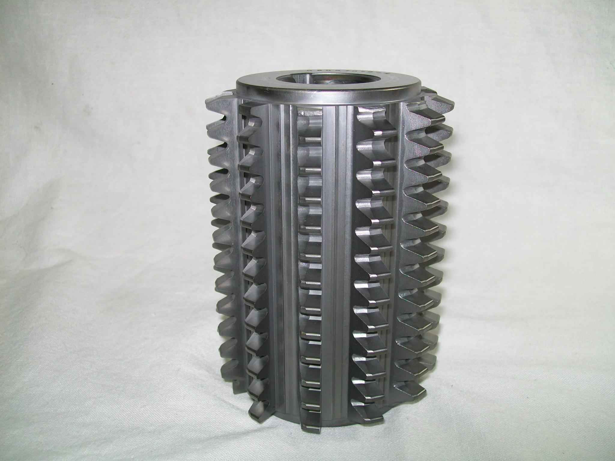
Milling cutters are cutting tools typically used in milling machines or machining centres to perform milling operations (and occasionally in other machine tools). They remove material by their movement within the machine (e.g., a ball nose mill) or directly from the cutter's shape (e.g., a form tool such as a hobbing cutter). Features Milling cutters come in several shapes and many sizes. There is also a choice of coatings, as well as rake angle and number of cutting surfaces. * Shape: Several standard shapes of milling cutters are used in industry today, which are explained in more detail below. * Flutes / teeth: The flutes of the milling bit are the deep helical grooves running up the cutter, while the sharp blade along the edge of the flute is known as the tooth. The tooth cuts the material, and chips of this material are pulled up the flute by the rotation of the cutter. There is almost always one tooth per flute, but some cutters have two teeth per flute. [...More Info...] [...Related Items...] OR: [Wikipedia] [Google] [Baidu] [Amazon] |
Cutter Location
A cutter location (CLData) refers to the position which a CNC milling machine has been instructed to hold a milling cutter by the instructions in the program (typically G-code). Each line of motion controlling G-code consists of two parts: the type of motion from the last cutter location to the next cutter location (e.g. "G01" means linear, "G02" means circular), and the next cutter location itself (the cartesian point (20, 1.3, 4.409) in this example). "G01 X20Y1.3Z4.409" The fundamental basis for creating the cutter paths suitable for CNC milling are functions that can find valid cutter locations, and stringing them together in a series. There are two broad and conflicting approaches to the problem of generating valid cutter locations, given a CAD model and a tool definition: calculation by offsets, and calculation against triangles. Each is discussed in a later section of this article. The most common example of the general cutter location problem is cutter radius compensatio ... [...More Info...] [...Related Items...] OR: [Wikipedia] [Google] [Baidu] [Amazon] |
