|
Frequency Compensation
In electronics engineering, frequency compensation is a technique used in amplifiers, and especially in amplifiers employing negative feedback. It usually has two primary goals: To avoid the unintentional creation of positive feedback, which will cause the amplifier to oscillate, and to control overshoot and ringing in the amplifier's step response. It is also used extensively to improve the bandwidth of single pole systems. Explanation Most amplifiers use negative feedback to trade gain for other desirable properties, such as decreased distortion, improved noise reduction or increased invariance to variation of parameters such as temperature. Ideally, the phase characteristic of an amplifier's frequency response would be linear; however, device limitations make this goal physically unattainable. More particularly, capacitances within the amplifier's gain stages cause the output signal to lag behind the input signal by up to 90° for each pole they create. If the sum of t ... [...More Info...] [...Related Items...] OR: [Wikipedia] [Google] [Baidu] |
Electronics Engineering
Electronic engineering is a sub-discipline of electrical engineering that emerged in the early 20th century and is distinguished by the additional use of active components such as semiconductor devices to amplify and control electric current flow. Previously electrical engineering only used passive devices such as mechanical switches, resistors, inductors, and capacitors. It covers fields such as analog electronics, digital electronics, consumer electronics, embedded systems and power electronics. It is also involved in many related fields, for example solid-state physics, radio engineering, telecommunications, control systems, signal processing, systems engineering, computer engineering, instrumentation engineering, electric power control, photonics and robotics. The Institute of Electrical and Electronics Engineers (IEEE) is one of the most important professional bodies for electronics engineers in the US; the equivalent body in the UK is the Institution of Engineering an ... [...More Info...] [...Related Items...] OR: [Wikipedia] [Google] [Baidu] |
Pole Splitting
Pole splitting is a phenomenon exploited in some forms of frequency compensation used in an electronic amplifier. When a capacitor is introduced between the input and output sides of the amplifier with the intention of moving the pole lowest in frequency (usually an input pole) to lower frequencies, pole splitting causes the pole next in frequency (usually an output pole) to move to a higher frequency. This pole movement increases the stability of the amplifier and improves its step response at the cost of decreased speed. Example of pole splitting This example shows that introducing capacitor CC in the amplifier of Figure 1 has two results: firstly, it causes the lowest frequency pole of the amplifier to move still lower in frequency and secondly, it causes the higher pole to move higher in frequency. This amplifier has a low frequency pole due to the added input resistance ''Ri'' and capacitance ''Ci'', with the time constant ''Ci'' ( ''RA , , Ri'' ). This pole is low ... [...More Info...] [...Related Items...] OR: [Wikipedia] [Google] [Baidu] |
Miller Effect
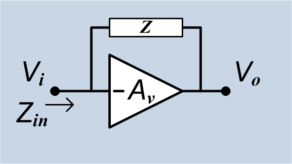
In electronics, the Miller effect (named after its discoverer John Milton Miller) accounts for the increase in the equivalent input capacitance of an inverting voltage amplifier due to amplification of the effect of capacitance between the amplifier's input and output terminals, and is given by :C_=C (1+A_v)\, where -A_v is the voltage gain of the inverting amplifier (A_v positive) and C is the feedback capacitance. Although the term ''Miller effect'' normally refers to capacitance, any impedance connected between the input and another node exhibiting gain can modify the amplifier input impedance via this effect. These properties of the Miller effect are generalized in the Miller theorem. The Miller capacitance due to undesired parasitic capacitance between the output and input of active devices like transistors and vacuum tubes is a major factor limiting their gain at high frequencies. History When Miller published his work in 1919, he was working on vacuum tube triodes. Th ... [...More Info...] [...Related Items...] OR: [Wikipedia] [Google] [Baidu] |
Lead–lag Compensator
A lead–lag compensator is a component in a control system that improves an undesirable frequency response in a feedback and control system. It is a fundamental building block in classical control theory. Applications Lead–lag compensators influence disciplines as varied as robotics, satellite control, automobile diagnostics, LCDs and laser frequency stabilisation. They are an important building block in analog control systems, and can also be used in digital control. Given the control plant, desired specifications can be achieved using compensators. I, P, PI, PD, and PID, are optimizing controllers which are used to improve system parameters (such as reducing steady state error, reducing resonant peak, improving system response by reducing rise time). All these operations can be done by compensators as well, used in cascade compensation technique. Theory Both lead compensators and lag compensators introduce a pole–zero pair into the open loop transfer function. T ... [...More Info...] [...Related Items...] OR: [Wikipedia] [Google] [Baidu] |
Zero (complex Analysis)
In complex analysis (a branch of mathematics), a pole is a certain type of singularity of a complex-valued function of a complex variable. It is the simplest type of non- removable singularity of such a function (see essential singularity). Technically, a point is a pole of a function if it is a zero of the function and is holomorphic (i.e. complex differentiable) in some neighbourhood of . A function is meromorphic in an open set if for every point of there is a neighborhood of in which at least one of and is holomorphic. If is meromorphic in , then a zero of is a pole of , and a pole of is a zero of . This induces a duality between ''zeros'' and ''poles'', that is fundamental for the study of meromorphic functions. For example, if a function is meromorphic on the whole complex plane plus the point at infinity, then the sum of the multiplicities of its poles equals the sum of the multiplicities of its zeros. Definitions A function of a complex variable ... [...More Info...] [...Related Items...] OR: [Wikipedia] [Google] [Baidu] |
Pole Splitting
Pole splitting is a phenomenon exploited in some forms of frequency compensation used in an electronic amplifier. When a capacitor is introduced between the input and output sides of the amplifier with the intention of moving the pole lowest in frequency (usually an input pole) to lower frequencies, pole splitting causes the pole next in frequency (usually an output pole) to move to a higher frequency. This pole movement increases the stability of the amplifier and improves its step response at the cost of decreased speed. Example of pole splitting This example shows that introducing capacitor CC in the amplifier of Figure 1 has two results: firstly, it causes the lowest frequency pole of the amplifier to move still lower in frequency and secondly, it causes the higher pole to move higher in frequency. This amplifier has a low frequency pole due to the added input resistance ''Ri'' and capacitance ''Ci'', with the time constant ''Ci'' ( ''RA , , Ri'' ). This pole is low ... [...More Info...] [...Related Items...] OR: [Wikipedia] [Google] [Baidu] |
Slew Rate
In electronics and electromagnetics, slew rate is defined as the change of voltage or current, or any other electrical or electromagnetic quantity, per unit of time. Expressed in SI units, the unit of measurement is given as the change per second, but in the context of electronic circuits a slew rate is usually expressed in terms of microseconds (μs) or nanoseconds (ns). Electronic circuits may specify minimum or maximum limits on the slew rates for their inputs or outputs, with these limits only valid under some set of given conditions (e.g. output loading). When given for the output of a circuit, such as an amplifier, the slew rate specification guarantees that the speed of the output signal transition will be at least the given minimum, or at most the given maximum. When applied to the input of a circuit, it instead indicates that the external driving circuitry needs to meet those limits in order to guarantee the correct operation of the receiving device. If these limits are ... [...More Info...] [...Related Items...] OR: [Wikipedia] [Google] [Baidu] |
Frequency Response In Dominant Pole Compensation
Frequency is the number of occurrences of a repeating event per unit of time. Frequency is an important parameter used in science and engineering to specify the rate of oscillatory and vibratory phenomena, such as mechanical vibrations, audio signals (sound), radio waves, and light. The interval of time between events is called the period. It is the reciprocal of the frequency. For example, if a heart beats at a frequency of 120 times per minute (2 hertz), its period is one half of a second. Special definitions of frequency are used in certain contexts, such as the angular frequency in rotational or cyclical properties, when the rate of angular progress is measured. Spatial frequency is defined for properties that vary or cccur repeatedly in geometry or space. The unit of measurement of frequency in the International System of Units (SI) is the hertz, having the symbol Hz. Definitions and units For cyclical phenomena such as oscillations, waves, or for examples o ... [...More Info...] [...Related Items...] OR: [Wikipedia] [Google] [Baidu] |
Diagram Of A Dominant Pole Compensated Open Loop Op-Amp
A diagram is a symbolic representation of information using visualization techniques. Diagrams have been used since prehistoric times on walls of caves, but became more prevalent during the Enlightenment. Sometimes, the technique uses a three-dimensional visualization which is then projected onto a two-dimensional surface. The word ''graph'' is sometimes used as a synonym for diagram. Overview The term "diagram" in its commonly used sense can have a general or specific meaning: * ''visual information device'' : Like the term "illustration", "diagram" is used as a collective term standing for the whole class of technical genres, including graphs, technical drawings and tables. * ''specific kind of visual display'' : This is the genre that shows qualitative data with shapes that are connected by lines, arrows, or other visual links. In science the term is used in both ways. For example, Anderson (1997) stated more generally: "diagrams are pictorial, yet abstract, representat ... [...More Info...] [...Related Items...] OR: [Wikipedia] [Google] [Baidu] |
Angular Frequency
In physics, angular frequency (symbol ''ω''), also called angular speed and angular rate, is a scalar measure of the angle rate (the angle per unit time) or the temporal rate of change of the phase argument of a sinusoidal waveform or sine function (for example, in oscillations and waves). Angular frequency (or angular speed) is the magnitude of the pseudovector quantity '' angular velocity''. (UP1) Angular frequency can be obtained multiplying '' rotational frequency'', ''ν'' (or ordinary ''frequency'', ''f'') by a full turn (2 radians): . It can also be formulated as , the instantaneous rate of change of the angular displacement, ''θ'', with respect to time, ''t''. (11 pages) Unit In SI[...More Info...] [...Related Items...] OR: [Wikipedia] [Google] [Baidu] |
Open-loop Gain
The open-loop gain of an electronic amplifier is the gain obtained when no overall feedback is used in the circuit. The open-loop gain of many electronic amplifiers is exceedingly high (by design) – an ''ideal'' operational amplifier (op-amp) has infinite open-loop gain. Typically an op-amp may have a maximal open-loop gain of around 10^5, or 100 dB. An op-amp with a large open-loop gain offers high precision when used as an inverting amplifier. Normally, negative feedback is applied around an amplifier with high open-loop gain, to reduce the gain of the complete circuit to a desired value. Definition The definition of open-loop gain (at a fixed frequency) is :A_\text = \frac, where V^ + -V^- is the input voltage difference that is being amplified. (The dependence on frequency is not displayed here.) Role in non-ideal gain The open-loop gain is a physical attribute of an operational amplifier that is often finite in comparison to the ideal gain. While open-loop gain is the ... [...More Info...] [...Related Items...] OR: [Wikipedia] [Google] [Baidu] |


