Process flow diagram on:
[Wikipedia]
[Google]
[Amazon]
A process flow diagram (PFD) is a diagram commonly used in


The PFD at ''The Engineering ToolBox''Kolmetz Handbook of Process Equipment Design: Process Flow Sheets
Chemical process engineering Piping Diagrams Process engineering
chemical
A chemical substance is a unique form of matter with constant chemical composition and characteristic properties. Chemical substances may take the form of a single element or chemical compounds. If two or more chemical substances can be combin ...
and process engineering to indicate the general flow of plant processes and equipment. The PFD displays the relationship between ''major'' equipment of a plant facility and does not show minor details such as piping details and designations. Another commonly used term for a PFD is ''process'' ''flowsheet''. It is the key document in process design.
Typical content of a process flow diagram
Typically, process flow diagrams of a single unit process include the following: * Processpiping
Within industry, piping is a system of pipes used to convey fluids (liquids and gases) from one location to another. The engineering discipline of piping design studies the efficient transport of fluid.
Industrial process piping (and accomp ...
* Major equipment items
*Connections with other systems
* Major bypass and recirculation (recycle) streams
* Operational data (temperature
Temperature is a physical quantity that quantitatively expresses the attribute of hotness or coldness. Temperature is measurement, measured with a thermometer. It reflects the average kinetic energy of the vibrating and colliding atoms making ...
, pressure
Pressure (symbol: ''p'' or ''P'') is the force applied perpendicular to the surface of an object per unit area over which that force is distributed. Gauge pressure (also spelled ''gage'' pressure)The preferred spelling varies by country and eve ...
, mass flow rate, density
Density (volumetric mass density or specific mass) is the ratio of a substance's mass to its volume. The symbol most often used for density is ''ρ'' (the lower case Greek letter rho), although the Latin letter ''D'' (or ''d'') can also be u ...
, etc.), often by stream references to a mass balance
* Process stream names
Process flow diagrams generally do not include:
* Pipe classes or piping line numbers
* Instrumentation details
* Minor bypass lines
* Instrumentation
* Controllers like Level Control or Flow Control
* Isolation and shutoff valve
A valve is a device or natural object that regulates, directs or controls the flow of a fluid (gases, liquids, fluidized solids, or Slurry, slurries) by opening, closing, or partially obstructing various passageways. Valves are technically Pip ...
s
* Maintenance vents and drains
* Relief
Relief is a sculpture, sculptural method in which the sculpted pieces remain attached to a solid background of the same material. The term ''wikt:relief, relief'' is from the Latin verb , to raise (). To create a sculpture in relief is to give ...
and safety valves
* Flange
A flange is a protruded ridge, lip or rim (wheel), rim, either external or internal, that serves to increase shear strength, strength (as the flange of a steel beam (structure), beam such as an I-beam or a T-beam); for easy attachment/transfer o ...
s
Process flow diagrams of multiple process units within a large industrial plant will usually contain less detail and may be called ''block flow diagrams'' or ''schematic flow diagrams''.
Process flow diagram examples
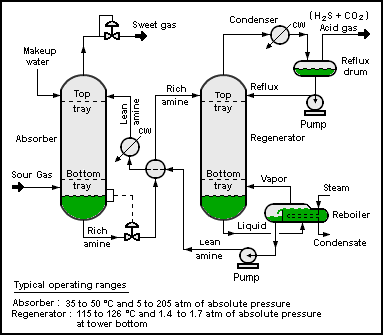
The process flow diagram below depicts a single chemical engineering unit process known as an amine treating plant:
Multiple process units within an industrial plant
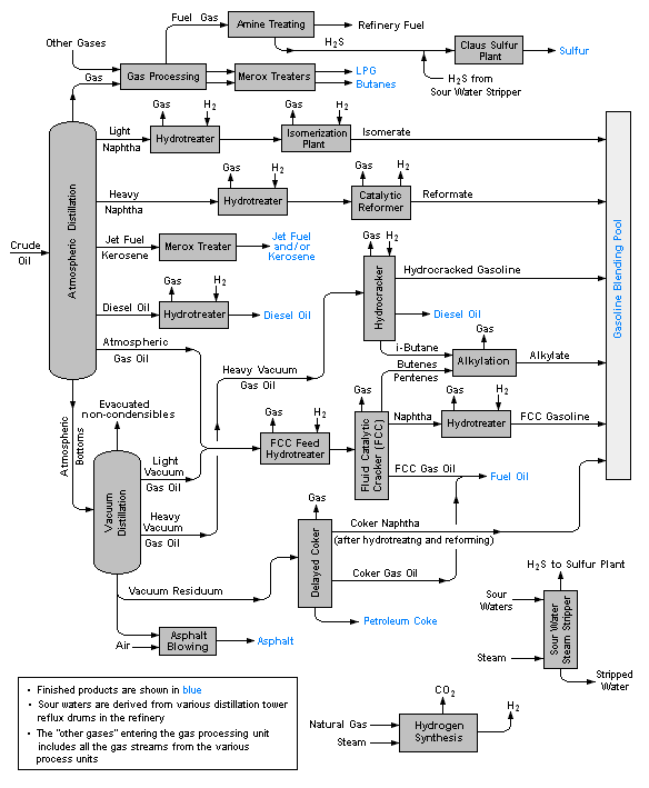
The process flow diagram below is an example of a schematic or block flow diagram and depicts the various unit processes within a typicaloil refinery
An oil refinery or petroleum refinery is an industrial processes, industrial process Factory, plant where petroleum (crude oil) is transformed and refining, refined into products such as gasoline (petrol), diesel fuel, Bitumen, asphalt base, ...
:

Other items of interest
A PFD can be computer generated from process simulators (see List of Chemical Process Simulators), CAD packages, or flow chart software using a library of chemical engineering symbols. Rules and symbols are available from standardization organizations such as DIN,ISO
The International Organization for Standardization (ISO ; ; ) is an independent, non-governmental, international standard development organization composed of representatives from the national standards organizations of member countries.
Me ...
or ANSI
The American National Standards Institute (ANSI ) is a private nonprofit organization that oversees the development of voluntary consensus standards for products, services, processes, systems, and personnel in the United States. The organiz ...
. Often PFDs are produced on large sheets of paper.
PFDs of many commercial processes can be found in the literature, specifically in encyclopedias of chemical technology, although some might be outdated. To find recent ones, patent databases such as those available from the United States Patent and Trademark Office
The United States Patent and Trademark Office (USPTO) is an List of federal agencies in the United States, agency in the United States Department of Commerce, U.S. Department of Commerce that serves as the national patent office and trademark ...
can be useful.
Standards
* ISO 15519-1:2010(en): Specification for diagrams for process industry — Part 1: General rules * ISO 15519-2:2015(en): Specifications for diagrams for process industry — Part 2: Measurement and control * ISO 10628-1:2014(en): Diagrams for the chemical and petrochemical industry — Part 1: Specification of diagrams * ISO 10628-2:2012(en): Diagrams for the chemical and petrochemical industry — Part 2: Graphical symbols * ANSI Y32.11: Graphical Symbols For Process Flow Diagrams (withdrawn 2003) * SAA AS 1109: Graphical Symbols For Process Flow Diagrams For The Food IndustrySee also
*HAZOP
A hazard and operability study (HAZOP) is a structured and systematic examination of a complex system, usually a process facility, in order to identify hazards to personnel, equipment or the environment, as well as operability problems that could ...
* Piping and instrumentation diagram
A Piping and Instrumentation Diagram (P&ID) is a detailed diagram in the process industry which shows process equipment together with the instrumentation and control devices. It is also called as mechanical flow diagram (MFD).
Superordinate to t ...
(P&ID)
* Symbolic language (engineering)
* Shit flow diagram
References
Further reading
* * * * *External links
{{commons category, Process flow diagramsThe PFD at ''The Engineering ToolBox''
Chemical process engineering Piping Diagrams Process engineering