|
H-bridge
An H-bridge is an electronic circuit that switches the polarity of a voltage applied to a load. These circuits are often used in robotics and other applications to allow DC motors to run forwards or backwards. The name is derived from its common schematic diagram representation, with four switching elements configured as the branches of a letter "H" and the load connected as the cross-bar. Most DC-to-AC converters (power inverters), most AC/AC converters, the DC-to-DC push–pull converter, isolated DC-to-DC converter most motor controllers, and many other kinds of power electronics use H bridges. In particular, a bipolar stepper motor is almost always driven by a motor controller containing two H bridges. General H-bridges are available as integrated circuits, or can be built from discrete components. The term ''H-bridge'' is derived from the typical graphical representation of such a circuit. An H-bridge is built with four switches (solid-state or mechanical). When the s ... [...More Info...] [...Related Items...] OR: [Wikipedia] [Google] [Baidu] |
Power Inverter
A power inverter, inverter, or invertor is a power electronic device or circuitry that changes direct current (DC) to alternating current (AC). The resulting AC frequency obtained depends on the particular device employed. Inverters do the opposite of rectifiers which were originally large electromechanical devices converting AC to DC. The input voltage, output voltage and frequency, and overall power handling depend on the design of the specific device or circuitry. The inverter does not produce any power; the power is provided by the DC source. A power inverter can be entirely electronic or maybe a combination of mechanical effects (such as a rotary apparatus) and electronic circuitry. Static inverters do not use moving parts in the conversion process. Power inverters are primarily used in electrical power applications where high currents and voltages are present; circuits that perform the same function for electronic signals, which usually have very low currents and vol ... [...More Info...] [...Related Items...] OR: [Wikipedia] [Google] [Baidu] |
Stepper Motor
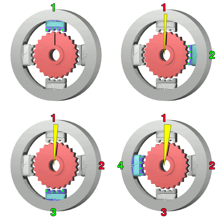
A stepper motor, also known as step motor or stepping motor,Clarence W. de Silva. Mechatronics: An Integrated Approach (2005). CRC Press. p. 675. "The terms ''stepper motor'', ''stepping motor'', and ''step motor'' are synonymous and are often used interchangeably." is a brushless DC electric motor that rotates in a series of small and discrete angular steps. Stepper motors can be set to any given step position without needing a Rotary encoder, position sensor for feedback. The step position can be rapidly increased or decreased to create continuous rotation, or the motor can be ordered to actively hold its position at one given step. Motors vary in size, speed, step resolution, and torque. Switched reluctance motors are very large stepping motors with a reduced pole count. They generally employ closed-loop commutator (electric), commutators. Mechanism Brushed DC motors rotate continuously when DC voltage is applied to their terminals. The stepper motor is known for its proper ... [...More Info...] [...Related Items...] OR: [Wikipedia] [Google] [Baidu] |
Push–pull Converter
A push–pull converter is a type of DC-to-DC converter, a switching converter that uses a transformer to change the voltage of a DC power supply. The distinguishing feature of a push-pull converter is that the transformer primary is supplied with current from the input line by pairs of transistors in a symmetrical push-pull circuit. The transistors are alternately switched on and off, periodically reversing the current in the transformer. Therefore, current is drawn from the line during both halves of the switching cycle. This contrasts with buck-boost converters, in which the input current is supplied by a single transistor which is switched on and off, so current is drawn from the line during only a part of the switching cycle. During the remainder of the cycle, the output power is supplied by energy stored in inductors or capacitors in the power supply. Push–pull converters have steadier input current, create less noise on the input line, and are more efficient in hig ... [...More Info...] [...Related Items...] OR: [Wikipedia] [Google] [Baidu] |
DC-to-DC Converter
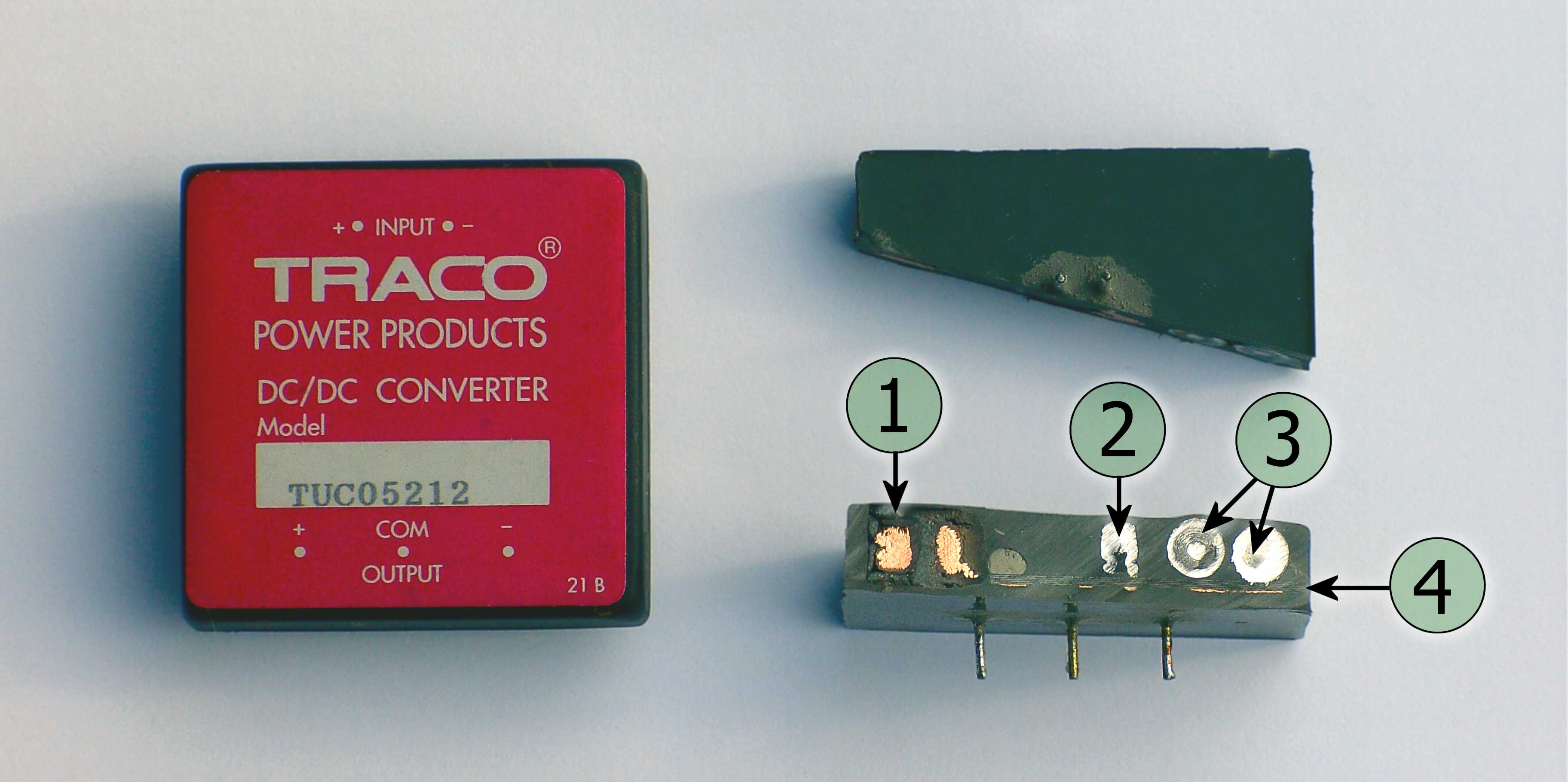
A DC-to-DC converter is an electronic circuit or electromechanical device that converts a source of direct current (DC) from one voltage level to another. It is a type of Electric power conversion, electric power converter. Power levels range from very low (small batteries) to very high (high-voltage power transmission). History Before the development of power semiconductors, one way to convert the voltage of a DC supply to a higher voltage, for low-power applications, was to convert it to AC by using a vibrator (electronic), vibrator, then by a step-up transformer, and finally a rectifier. Where higher power was needed, a motor–generator unit was often used, in which an electric motor drove a generator that produced the desired voltage. (The motor and generator could be separate devices, or they could be combined into a single "dynamotor" unit with no external power shaft.) These relatively inefficient and expensive designs were used only when there was no alternative, as to po ... [...More Info...] [...Related Items...] OR: [Wikipedia] [Google] [Baidu] |
Switch
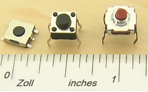
In electrical engineering, a switch is an electrical component that can disconnect or connect the conducting path in an electrical circuit, interrupting the electric current or diverting it from one conductor to another. The most common type of switch is an electromechanical device consisting of one or more sets of movable electrical contacts connected to external circuits. When a pair of contacts is touching current can pass between them, while when the contacts are separated no current can flow. Switches are made in many different configurations; they may have multiple sets of contacts controlled by the same knob or actuator, and the contacts may operate simultaneously, sequentially, or alternately. A switch may be operated manually, for example, a light switch or a keyboard button, or may function as a sensing element to sense the position of a machine part, liquid level, pressure, or temperature, such as a thermostat. Many specialized forms exist, such as the toggle swit ... [...More Info...] [...Related Items...] OR: [Wikipedia] [Google] [Baidu] |
Synchronous Rectifier
Active rectification, or synchronous rectification, is a technique for improving the efficiency of rectification by replacing diodes with actively controlled switches, usually power MOSFETs or power bipolar junction transistors (BJT). Whereas normal semiconductor diodes have a roughly fixed voltage drop of around 0.5 to 1 volts, active rectifiers behave as resistances, and can have arbitrarily low voltage drop. Historically, vibrator-driven switches or motor-driven commutators have also been used for mechanical rectifiers and synchronous rectification. Active rectification has many applications. It is frequently used for arrays of photovoltaic panels to avoid reverse current flow that can cause overheating with partial shading while giving minimum power loss. It is also used in switched-mode power supplies (SMPS). Motivation The constant voltage drop of a standard p-n junction diode is typically between 0.7 V and 1.7 V, causing significant power loss in the di ... [...More Info...] [...Related Items...] OR: [Wikipedia] [Google] [Baidu] |
Relay
A relay Electromechanical relay schematic showing a control coil, four pairs of normally open and one pair of normally closed contacts An automotive-style miniature relay with the dust cover taken off A relay is an electrically operated switch. It has a set of input terminals for one or more control signals, and a set of operating contact terminals. The switch may have any number of contacts in multiple contact forms, such as make contacts, break contacts, or combinations thereof. Relays are used to control a circuit by an independent low-power signal and to control several circuits by one signal. They were first used in long-distance telegraph circuits as signal repeaters that transmit a refreshed copy of the incoming signal onto another circuit. Relays were used extensively in telephone exchanges and early computers to perform logical operations. The traditional electromechanical relay uses an electromagnet to close or open the contacts, but relays using other operati ... [...More Info...] [...Related Items...] OR: [Wikipedia] [Google] [Baidu] |
Zener Diode
A Zener diode is a type of diode designed to exploit the Zener effect to affect electric current to flow against the normal direction from anode to cathode, when the voltage across its terminals exceeds a certain characteristic threshold, the ''Zener voltage''. Zener diodes are manufactured with a variety of Zener voltages, including variable devices. Some types have an abrupt, heavily doped p–n junction with a low Zener voltage, in which case the reverse conduction occurs due to electron quantum tunnelling in the short distance between p and n regions. Diodes with a higher Zener voltage have more lightly doped junctions, causing their mode of operation to involve avalanche breakdown. Both breakdown types are present in Zener diodes with the Zener effect predominating at lower voltages and avalanche breakdown at higher voltages. Zener diodes are used to generate low-power stabilized supply rails from higher voltages and to provide reference voltages for circuits, especially sta ... [...More Info...] [...Related Items...] OR: [Wikipedia] [Google] [Baidu] |
Flyback Converter
The flyback converter is used in both AC/DC conversion, AC/DC, and DC-DC conversion, DC/DC conversion with galvanic isolation between the input and any outputs. The flyback converter is a buck-boost converter with the inductor split to form a transformer, so that the voltage ratios are multiplied with an additional advantage of isolation. Structure and principle The schematic of a flyback converter is shown in Fig. 1. It is equivalent to that of a buck–boost converter, with the inductor split to form a transformer. Therefore, the operating principle of both converters is very similar: * When the switch is closed (top of Fig. 2), the primary of the transformer is directly connected to the input voltage source. The primary current and magnetic flux in the transformer increases, storing energy in the transformer. The voltage induced in the secondary winding is negative, so the diode is reverse-biased (i.e., blocked). The output capacitor supplies energy to the output load. * Wh ... [...More Info...] [...Related Items...] OR: [Wikipedia] [Google] [Baidu] |
Leakage Inductance
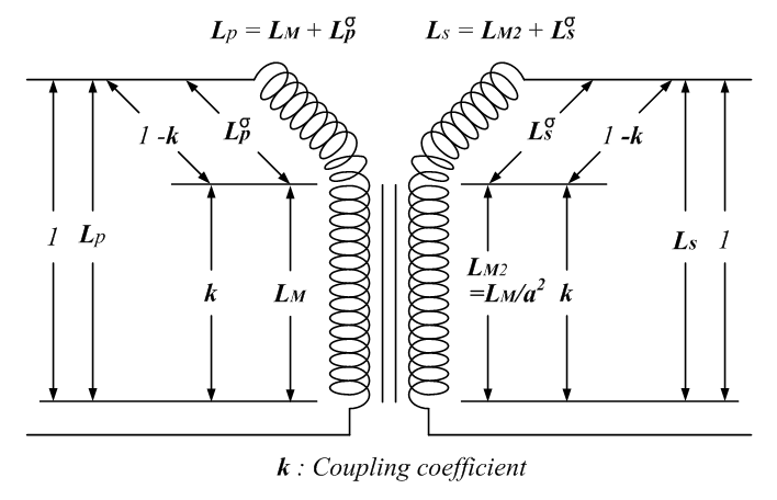
Leakage inductance derives from the electrical property of an imperfectly coupled transformer whereby each Electromagnetic coil, winding behaves as a self-inductance in series and parallel circuits, series with the winding's respective Electrical resistance and conductance, ohmic resistance constant. These four winding constants also interact with the transformer's mutual inductance. The winding leakage inductance is due to leakage flux not linking with all turns of each imperfectly coupled winding. Leakage reactance is usually the most important element of a power system transformer due to power factor, voltage drop, reactive power consumption and Fault (power engineering), fault current considerations. Leakage inductance depends on the geometry of the core and the windings. Voltage drop across the inductive reactance, leakage reactance results in often undesirable supply regulation with varying transformer load. But it can also be useful for Harmonics (electrical power), harmonic ... [...More Info...] [...Related Items...] OR: [Wikipedia] [Google] [Baidu] |


